How to Use 130DC Fan Motor w/o blades: Examples, Pinouts, and Specs
Introduction
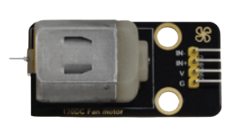
The 130DC Fan Motor w/o Blades (Manufacturer: Keyestudio, Part ID: Fan four pin) is a compact and versatile DC motor designed for cooling and ventilation applications. This motor operates on direct current and is ideal for projects requiring a customizable fan blade setup. Its small size and efficient performance make it suitable for use in electronics cooling, robotics, and DIY projects.
Explore Projects Built with 130DC Fan Motor w/o blades


Explore Projects Built with 130DC Fan Motor w/o blades
Common Applications and Use Cases
- Cooling systems for electronic devices (e.g., microcontrollers, power supplies)
- Ventilation in small enclosures or cases
- Robotics projects requiring airflow
- Custom fan designs for specific applications
Technical Specifications
The following table outlines the key technical details of the 130DC Fan Motor w/o Blades:
| Parameter | Specification |
|---|---|
| Operating Voltage | 3V to 6V DC |
| Rated Current | 0.2A (200mA) |
| Maximum Current | 0.35A (350mA) |
| Power Consumption | 1.2W (at 6V) |
| Motor Speed | ~10,000 RPM (at 6V, no load) |
| Dimensions | 15mm x 20mm x 25mm |
| Weight | ~15g |
| Shaft Diameter | 2mm |
| Shaft Length | 10mm |
Pin Configuration and Descriptions
The motor features a four-pin connector for easy integration into circuits. The pin configuration is as follows:
| Pin | Name | Description |
|---|---|---|
| 1 | VCC (+) | Positive power supply terminal (3V to 6V DC). |
| 2 | GND (-) | Ground terminal for the power supply. |
| 3 | PWM Input | Pulse Width Modulation (PWM) input for speed control. |
| 4 | FG (Tachometer) | Feedback signal for monitoring motor speed (optional use). |
Usage Instructions
How to Use the Component in a Circuit
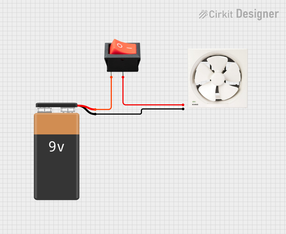
- Power Supply: Connect the VCC pin to a DC power source (3V to 6V) and the GND pin to the ground of the power source.
- Speed Control: Use the PWM input pin to control the motor speed. A PWM signal with a duty cycle of 0% to 100% adjusts the speed from 0 RPM to maximum RPM.
- Speed Monitoring: Optionally, connect the FG pin to a microcontroller or monitoring circuit to measure the motor's speed. The FG pin outputs a square wave signal proportional to the motor's RPM.
Important Considerations and Best Practices
- Voltage Range: Ensure the input voltage does not exceed 6V to prevent damage to the motor.
- Current Requirements: Use a power supply capable of providing at least 350mA to handle peak current demands.
- Heat Dissipation: Avoid prolonged operation at maximum speed to prevent overheating.
- Blade Installation: Ensure the fan blades are securely attached to the motor shaft and balanced to avoid vibration.
- PWM Signal: Use a PWM frequency between 1kHz and 10kHz for optimal speed control.
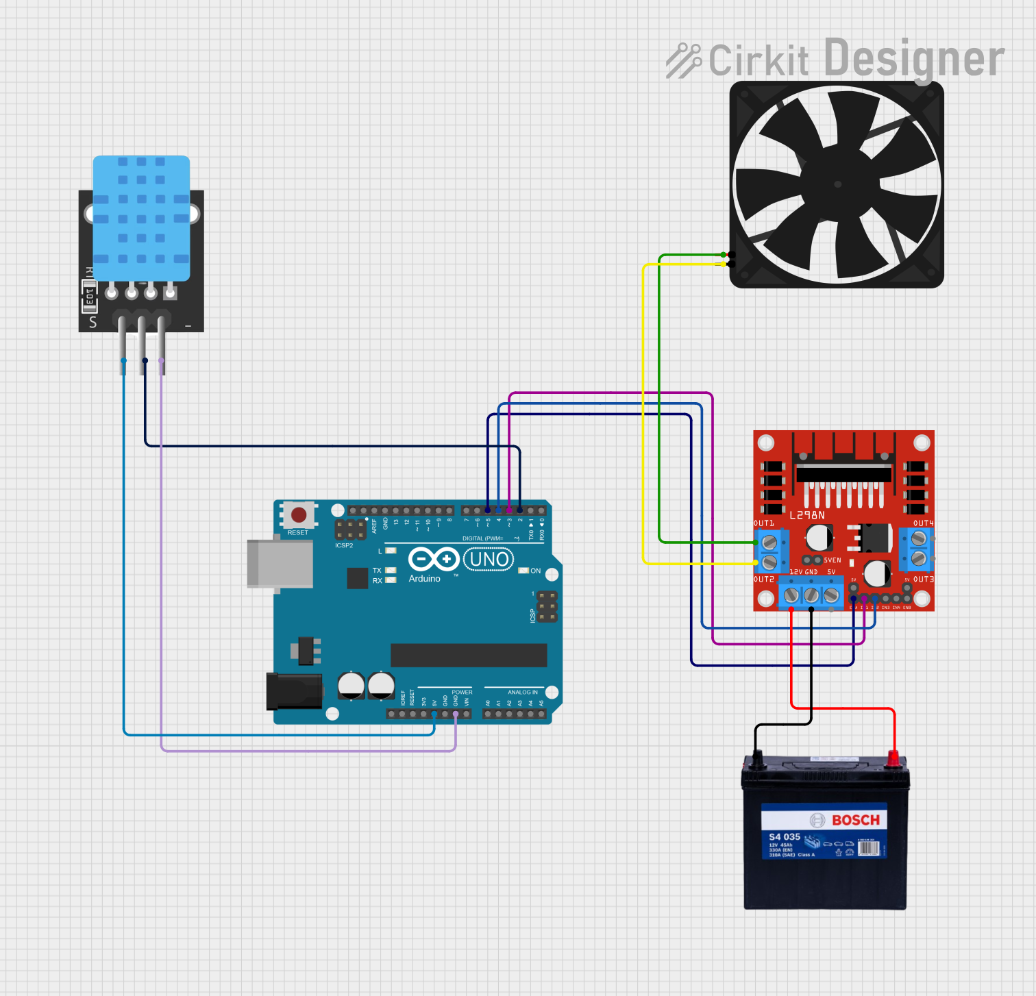
Example: Connecting to an Arduino UNO
The 130DC Fan Motor can be controlled using an Arduino UNO. Below is an example code to control the motor speed using PWM:
// Define the PWM pin connected to the motor's PWM input
const int motorPWMPin = 9; // Pin 9 on Arduino UNO

void setup() {
  // Set the motor PWM pin as an output
  pinMode(motorPWMPin, OUTPUT);
}

void loop() {
  // Gradually increase motor speed
  for (int speed = 0; speed <= 255; speed += 5) {
    analogWrite(motorPWMPin, speed); // Set PWM duty cycle
    delay(50); // Wait 50ms
  }

  // Gradually decrease motor speed
  for (int speed = 255; speed >= 0; speed -= 5) {
    analogWrite(motorPWMPin, speed); // Set PWM duty cycle
    delay(50); // Wait 50ms
  }
}
Note: Ensure the motor's VCC and GND pins are connected to an external power source, as the Arduino's 5V pin may not provide sufficient current.
Troubleshooting and FAQs
Common Issues and Solutions
Motor Does Not Spin
- Cause: Insufficient power supply or incorrect wiring.
- Solution: Verify the power supply voltage and current. Check all connections.
Motor Overheats
- Cause: Prolonged operation at maximum speed or excessive load.
- Solution: Reduce the duty cycle of the PWM signal or allow the motor to cool periodically.
Unstable Speed
- Cause: Incorrect PWM frequency or noisy power supply.
- Solution: Use a PWM frequency between 1kHz and 10kHz. Add a capacitor across the power supply terminals to reduce noise.
No Feedback Signal from FG Pin
- Cause: FG pin not connected or motor not spinning.
- Solution: Ensure the FG pin is connected to a microcontroller input pin. Verify the motor is powered and spinning.
FAQs
Can I use this motor with a 12V power supply? No, the motor is designed for a maximum voltage of 6V. Using a higher voltage may damage the motor.
What type of fan blades can I use with this motor? Any fan blade with a 2mm shaft hole can be used. Ensure the blades are balanced to avoid vibration.
Can I control the motor without a PWM signal? Yes, the motor will run at full speed if the PWM pin is left unconnected or tied to VCC.
Is the FG pin necessary for operation? No, the FG pin is optional and only used for speed monitoring. The motor will function without it.
This concludes the documentation for the 130DC Fan Motor w/o Blades. For further assistance, refer to the manufacturer's datasheet or contact Keyestudio support.