How to Use DC jack: Examples, Pinouts, and Specs
Introduction
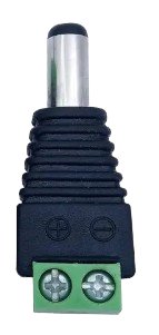
A DC jack is a type of electrical connector used to supply direct current (DC) power to electronic devices. It typically consists of a cylindrical socket that accepts a matching plug, allowing for easy connection and disconnection of power sources. DC jacks are widely used in consumer electronics, such as laptops, portable devices, and small appliances, to provide a reliable and standardized method of delivering power.
Explore Projects Built with DC jack


Explore Projects Built with DC jack
Common Applications and Use Cases
- Powering laptops, routers, and other consumer electronics
- Supplying power to Arduino and other microcontroller-based projects
- Connecting external power supplies to small appliances
- Prototyping circuits that require a stable DC power source
Technical Specifications
Below are the general technical specifications for a standard DC jack. Note that specific models may vary slightly, so always refer to the datasheet of the exact component you are using.
Key Technical Details
- Voltage Rating: Typically 12V to 24V (varies by model)
- Current Rating: Commonly 1A to 5A
- Connector Type: Cylindrical socket
- Outer Diameter: Common sizes include 5.5mm, 3.5mm, or 2.1mm
- Inner Diameter: Typically 2.1mm or 2.5mm
- Polarity: Center pin is usually positive (+), and the outer sleeve is negative (-)
Pin Configuration and Descriptions
The DC jack typically has three pins:
| Pin Name | Description |
|---|---|
| Center Pin | Connects to the positive terminal of the power supply. |
| Outer Sleeve | Connects to the negative terminal of the power supply. |
| Switch Pin | Optional pin used to detect whether a plug is inserted or to disconnect a load. |
Usage Instructions
How to Use the DC Jack in a Circuit
- Identify the Polarity: Ensure that the center pin is connected to the positive terminal of the power source and the outer sleeve to the negative terminal. Reversing polarity can damage your circuit.
- Mounting the Jack: Secure the DC jack to your PCB or enclosure. Many DC jacks are panel-mounted, requiring a hole in the enclosure for installation.
- Soldering Connections:
- Solder the center pin to the positive rail of your circuit.
- Solder the outer sleeve to the ground (GND) rail.
- If using the switch pin, connect it to the load or detection circuit as needed.
- Testing: Before powering your circuit, use a multimeter to verify the connections and polarity.
Important Considerations and Best Practices
- Voltage and Current Ratings: Ensure the DC jack can handle the voltage and current requirements of your circuit.
- Polarity Protection: Use a diode or polarity protection circuit to prevent damage from incorrect connections.
- Secure Connections: Ensure all solder joints are clean and secure to avoid intermittent connections.
- Heat Dissipation: If the DC jack is used in high-current applications, ensure proper ventilation or heat dissipation.
Example: Connecting a DC Jack to an Arduino UNO
Below is an example of how to connect a DC jack to an Arduino UNO for powering the board.
Circuit Diagram
- Connect the center pin of the DC jack to the Arduino's VIN pin.
- Connect the outer sleeve of the DC jack to the Arduino's GND pin.
Sample Code
The following code demonstrates a simple LED blink program for an Arduino UNO powered via a DC jack.
// Simple LED Blink Program
// This code assumes an LED is connected to pin 13 of the Arduino UNO.

void setup() {
  pinMode(13, OUTPUT); // Set pin 13 as an output for the LED
}

void loop() {
  digitalWrite(13, HIGH); // Turn the LED on
  delay(1000);            // Wait for 1 second
  digitalWrite(13, LOW);  // Turn the LED off
  delay(1000);            // Wait for 1 second
}
Troubleshooting and FAQs
Common Issues and Solutions
No Power to the Circuit:
- Cause: Incorrect polarity or loose connections.
- Solution: Verify the polarity of the DC jack and ensure all connections are secure.
Overheating of the DC Jack:
- Cause: Exceeding the current rating of the jack.
- Solution: Use a DC jack with a higher current rating or reduce the load on the circuit.
Intermittent Power Loss:
- Cause: Poor solder joints or a loose plug.
- Solution: Re-solder the connections and ensure the plug fits snugly into the jack.
Circuit Not Working After Connection:
- Cause: Reversed polarity or damaged components.
- Solution: Check the polarity with a multimeter and inspect the circuit for damaged parts.
FAQs
Q: Can I use a DC jack with a higher voltage rating than my power supply?
A: Yes, as long as the voltage rating of the DC jack exceeds the voltage of your power supply, it is safe to use.
Q: How do I determine the size of the DC jack I need?
A: Measure the outer and inner diameters of the plug you intend to use, and select a matching DC jack.
Q: Is it necessary to use the switch pin?
A: No, the switch pin is optional and is typically used for advanced applications, such as detecting when a plug is inserted.
Q: Can I use a DC jack for AC power?
A: No, DC jacks are designed specifically for direct current (DC) and should not be used for alternating current (AC).