How to Use Dual JKFF: Examples, Pinouts, and Specs
Introduction
The Dual JK Flip-Flop (JKFF) is a digital memory circuit that integrates two JK flip-flops into a single package. Each flip-flop can store one bit of data, making it a versatile component in sequential logic circuits. The JK flip-flop is an edge-triggered device, meaning it changes state based on the clock signal's edge (rising or falling). It is widely used in counters, shift registers, frequency dividers, and other digital systems requiring data storage and manipulation.
Explore Projects Built with Dual JKFF

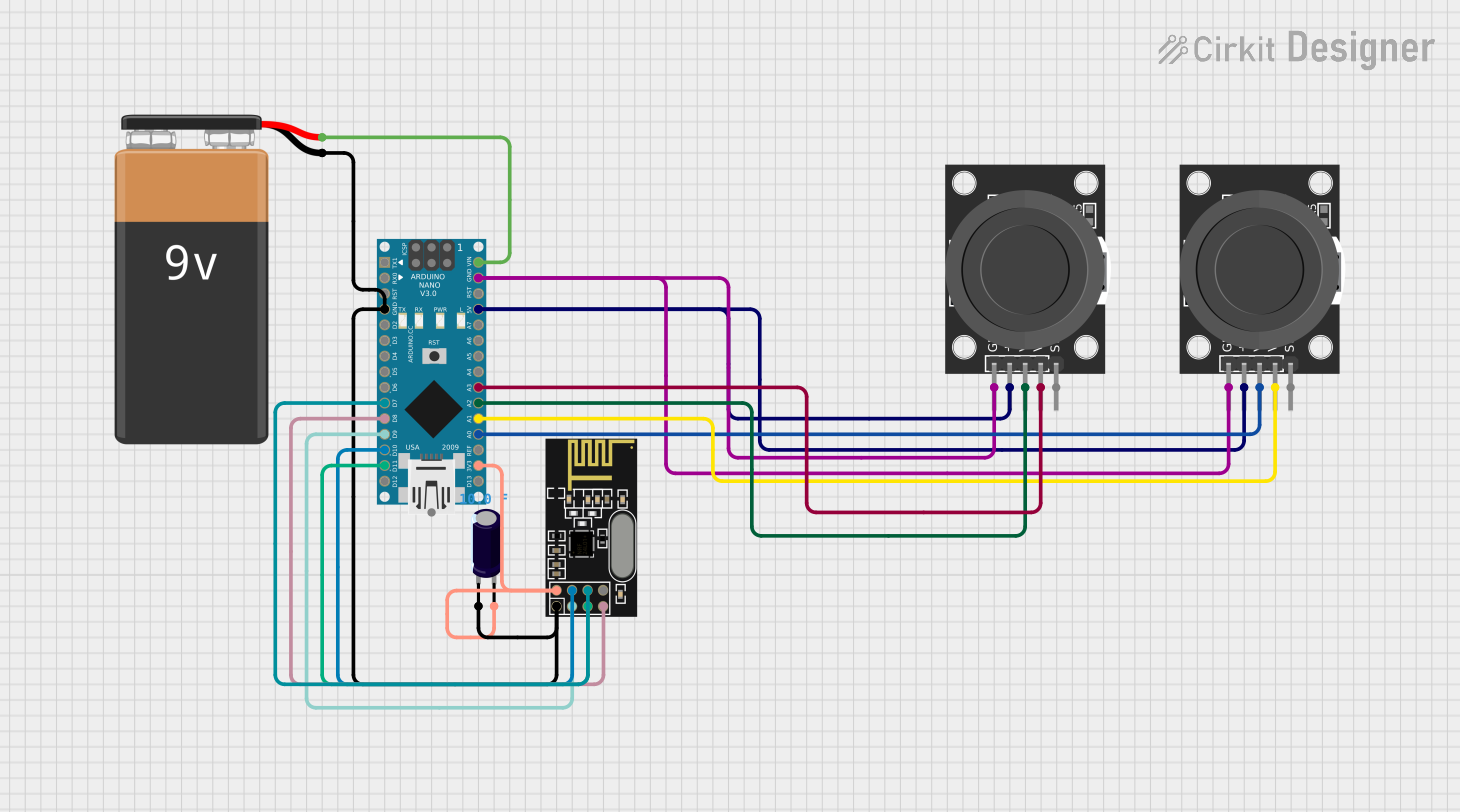

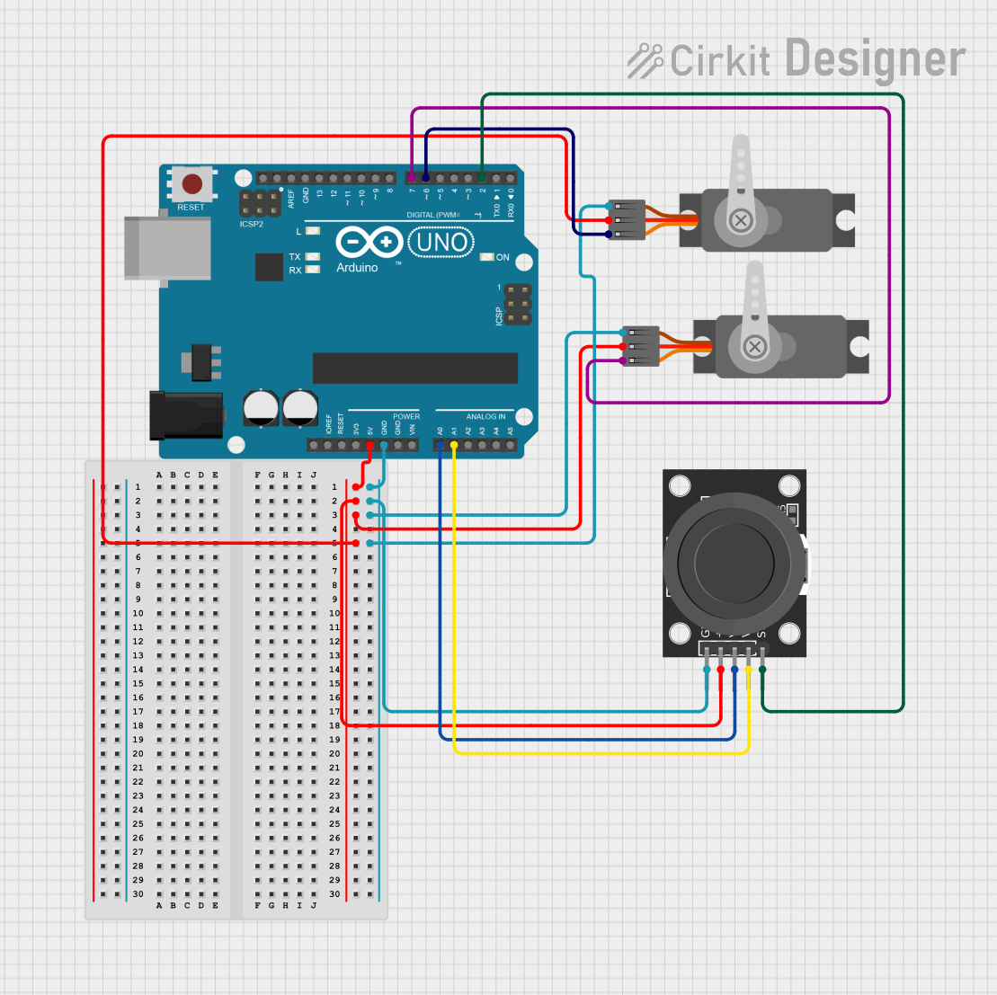
Explore Projects Built with Dual JKFF
Common Applications:
- Counters: Used in binary and decade counters for counting operations.
- Shift Registers: Facilitates data shifting in serial-to-parallel or parallel-to-serial conversions.
- Frequency Division: Divides the input clock frequency by a factor of 2 or more.
- State Machines: Implements sequential logic in finite state machines.
- Data Storage: Temporarily stores binary data in digital systems.
Technical Specifications
Key Technical Details:
- Supply Voltage (Vcc): Typically 3V to 15V (varies by specific IC model).
- Input Voltage (VI): 0V to Vcc.
- Output Voltage (VO): 0V to Vcc.
- Clock Trigger: Edge-triggered (rising or falling edge, depending on the IC).
- Propagation Delay: Typically 10ns to 50ns (varies by model and supply voltage).
- Power Consumption: Low power consumption, typically in the milliwatt range.
- Package Types: Commonly available in DIP, SOIC, or other IC packages.
Pin Configuration and Descriptions:
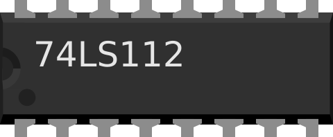
Below is the pin configuration for a typical Dual JK Flip-Flop IC, such as the 74LS73.
| Pin Number | Pin Name | Description |
|---|---|---|
| 1 | 1J | J input for Flip-Flop 1 |
| 2 | 1K | K input for Flip-Flop 1 |
| 3 | 1CLK | Clock input for Flip-Flop 1 |
| 4 | 1CLR | Clear (reset) input for Flip-Flop 1 (active LOW) |
| 5 | 1Q | Q output for Flip-Flop 1 |
| 6 | 1Q̅ | Complement (inverted) Q output for Flip-Flop 1 |
| 7 | GND | Ground (0V) |
| 8 | 2Q̅ | Complement (inverted) Q output for Flip-Flop 2 |
| 9 | 2Q | Q output for Flip-Flop 2 |
| 10 | 2CLR | Clear (reset) input for Flip-Flop 2 (active LOW) |
| 11 | 2CLK | Clock input for Flip-Flop 2 |
| 12 | 2K | K input for Flip-Flop 2 |
| 13 | 2J | J input for Flip-Flop 2 |
| 14 | Vcc | Positive supply voltage |
Usage Instructions
How to Use the Dual JK Flip-Flop in a Circuit:
- Power Supply: Connect the Vcc pin to a suitable voltage source (e.g., 5V for 74LS73) and the GND pin to ground.
- Inputs:
- Connect the J and K inputs to the desired logic levels (HIGH or LOW).
- Provide a clock signal to the CLK pin. The flip-flop will toggle or change state on the clock's edge.
- Outputs:
- The Q and Q̅ outputs represent the stored data and its complement, respectively.
- Use these outputs to drive other components or logic circuits.
- Clear Function:
- To reset the flip-flop, apply a LOW signal to the CLR pin. This forces Q to LOW and Q̅ to HIGH.
- Edge Triggering: Ensure the clock signal is clean and free of noise to avoid unintended state changes.
Important Considerations:
- Debouncing: If using a mechanical switch for the clock input, debounce the signal to prevent erratic behavior.
- Unused Inputs: Tie unused J and K inputs to a defined logic level (HIGH or LOW) to avoid floating inputs.
- Timing Constraints: Ensure the setup and hold times for the J and K inputs are met relative to the clock edge.
- Load Capacitance: Avoid excessive load capacitance on the outputs to maintain proper signal integrity.
Example: Connecting to an Arduino UNO
The Dual JK Flip-Flop can be interfaced with an Arduino UNO to demonstrate its functionality. Below is an example code to toggle the flip-flop's state using a clock signal generated by the Arduino.
// Example: Toggling a JK Flip-Flop using Arduino UNO
// Pin Definitions
const int clockPin = 9;  // Arduino pin connected to the CLK input of the JKFF
const int jPin = 10;     // Arduino pin connected to the J input of the JKFF
const int kPin = 11;     // Arduino pin connected to the K input of the JKFF

void setup() {
  pinMode(clockPin, OUTPUT); // Set clock pin as output
  pinMode(jPin, OUTPUT);     // Set J pin as output
  pinMode(kPin, OUTPUT);     // Set K pin as output

  // Initialize J and K inputs to HIGH
  digitalWrite(jPin, HIGH);
  digitalWrite(kPin, HIGH);
}

void loop() {
  // Generate a clock pulse
  digitalWrite(clockPin, HIGH); // Set clock HIGH
  delay(500);                   // Wait for 500ms
  digitalWrite(clockPin, LOW);  // Set clock LOW
  delay(500);                   // Wait for 500ms
}
Notes:
- Connect the Arduino's GND to the JKFF's GND.
- Ensure the JKFF's Vcc matches the Arduino's logic level (5V for most Arduino boards).
Troubleshooting and FAQs
Common Issues:
Flip-Flop Not Responding to Clock Signal:
- Cause: Clock signal is noisy or improperly connected.
- Solution: Use a clean clock signal and verify the connection.
Unexpected Output States:
- Cause: Floating J or K inputs.
- Solution: Tie unused inputs to a defined logic level (HIGH or LOW).
Flip-Flop Stuck in Reset State:
- Cause: CLR pin is held LOW.
- Solution: Ensure the CLR pin is HIGH during normal operation.
Propagation Delay Issues:
- Cause: Exceeding the IC's timing specifications.
- Solution: Verify the clock frequency and input timing constraints.
FAQs:
Q: Can I use the Dual JK Flip-Flop with a 3.3V system?
A: Yes, provided the specific IC model supports 3.3V operation. Check the datasheet.Q: What happens if both J and K are HIGH?
A: The flip-flop toggles its state on each clock edge.Q: Can I cascade multiple JK flip-flops?
A: Yes, you can connect the Q output of one flip-flop to the clock or input of another for sequential operations.Q: How do I debounce a mechanical clock input?
A: Use a capacitor and resistor in an RC circuit or implement software debouncing if using a microcontroller.
This documentation provides a comprehensive guide to understanding, using, and troubleshooting the Dual JK Flip-Flop in various applications.