Cirkit Designer Logo
Cirkit Designer
Your all-in-one circuit design IDE
Home / 
Component Documentation

How to Use Adafruit PCF8574 I2C GPIO Expander Breakout: Examples, Pinouts, and Specs

Image of Adafruit PCF8574 I2C GPIO Expander Breakout
Cirkit Designer LogoDesign with Adafruit PCF8574 I2C GPIO Expander Breakout in Cirkit Designer

Introduction

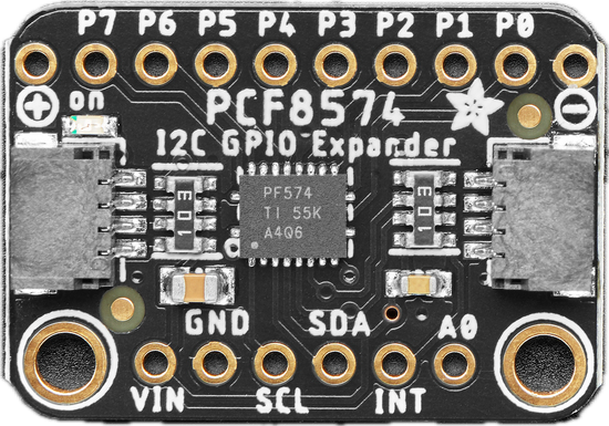
The Adafruit PCF8574 I2C GPIO Expander Breakout (Part ID: 5545) is a versatile module designed to expand the number of digital input/output (GPIO) pins available to your microcontroller. It communicates via the I2C protocol, allowing you to control up to 8 additional GPIO pins with minimal wiring. This breakout is ideal for projects requiring more GPIOs than your microcontroller natively provides, such as controlling LEDs, reading button states, or interfacing with other digital devices.

Explore Projects Built with Adafruit PCF8574 I2C GPIO Expander Breakout

Use Cirkit Designer to design, explore, and prototype these projects online. Some projects support real-time simulation. Click "Open Project" to start designing instantly!
ESP32-Based I2C Communication Hub with Multiplexer and Expander
Image of Lights: A project utilizing Adafruit PCF8574 I2C GPIO Expander Breakout in a practical application
This circuit features an Olimex ESP32-EVB microcontroller unit (MCU) for processing and connectivity, interfaced with an MCP23017 I/O expander and an Adafruit TCA9548A I2C multiplexer to expand the number of I/O lines and allow multiple I2C devices to communicate with the MCU over the same bus. Pull-up resistors are connected to the I2C lines for proper bus operation, and both the MCP23017 and TCA9548A have their reset lines pulled high, likely for normal operation without external reset control.
Cirkit Designer LogoOpen Project in Cirkit Designer
MCP23017-Expanded I/O Interface with ADS1115 ADC and ESP32 Control
Image of door and window sensors: A project utilizing Adafruit PCF8574 I2C GPIO Expander Breakout in a practical application
This circuit features two MCP23017 I/O expanders interfaced with multiple switches, allowing for the expansion of input capabilities. The MCP23017s are connected via I2C to an Olimex ESP32-EVB microcontroller, which likely manages the input states from the switches. Additionally, an Adafruit ADS1115 16-bit ADC is included, suggesting that some analog inputs are being monitored, with the ADC also interfaced with the ESP32 via I2C.
Cirkit Designer LogoOpen Project in Cirkit Designer
Raspberry Pi-Controlled Dual Servo Driver with PCA9685 Interface
Image of Copy of PWM, SERVO, ESC Wiring: A project utilizing Adafruit PCF8574 I2C GPIO Expander Breakout in a practical application
This circuit controls two servomotors (MG996R and MG995) using a Raspberry Pi 5 and an Adafruit PCA9685 PWM Servo Breakout board. The Raspberry Pi communicates with the PCA9685 via I2C (using GPIO 2 and GPIO 3 for SDA and SCL, respectively) to send PWM signals to the servos. Power distribution is managed through an Adafruit Perma Proto Small Mint board, which connects the 5V and GND from the Raspberry Pi to the PCA9685 and the servos.
Cirkit Designer LogoOpen Project in Cirkit Designer
I2C-Controlled Relay Switching with ESP32 and MCP23017 for Home Automation
Image of Vloerverwarming: A project utilizing Adafruit PCF8574 I2C GPIO Expander Breakout in a practical application
This circuit appears to be a control system utilizing two MCP23017 I/O expanders interfaced with an Olimex ESP32-EVB microcontroller via I2C communication, as indicated by the SDA and SCL connections with pull-up resistors. The MCP23017 expanders control an 8-channel relay module, allowing the microcontroller to switch various loads, potentially for home automation or industrial control. Additionally, there is an Adafruit ADS1115 16-bit ADC for analog signal measurement, and several heating actuators and a thermostat are connected, suggesting temperature control functionality.
Cirkit Designer LogoOpen Project in Cirkit Designer

Explore Projects Built with Adafruit PCF8574 I2C GPIO Expander Breakout

Use Cirkit Designer to design, explore, and prototype these projects online. Some projects support real-time simulation. Click "Open Project" to start designing instantly!
Image of Lights: A project utilizing Adafruit PCF8574 I2C GPIO Expander Breakout in a practical application
ESP32-Based I2C Communication Hub with Multiplexer and Expander
This circuit features an Olimex ESP32-EVB microcontroller unit (MCU) for processing and connectivity, interfaced with an MCP23017 I/O expander and an Adafruit TCA9548A I2C multiplexer to expand the number of I/O lines and allow multiple I2C devices to communicate with the MCU over the same bus. Pull-up resistors are connected to the I2C lines for proper bus operation, and both the MCP23017 and TCA9548A have their reset lines pulled high, likely for normal operation without external reset control.
Cirkit Designer LogoOpen Project in Cirkit Designer
Image of door and window sensors: A project utilizing Adafruit PCF8574 I2C GPIO Expander Breakout in a practical application
MCP23017-Expanded I/O Interface with ADS1115 ADC and ESP32 Control
This circuit features two MCP23017 I/O expanders interfaced with multiple switches, allowing for the expansion of input capabilities. The MCP23017s are connected via I2C to an Olimex ESP32-EVB microcontroller, which likely manages the input states from the switches. Additionally, an Adafruit ADS1115 16-bit ADC is included, suggesting that some analog inputs are being monitored, with the ADC also interfaced with the ESP32 via I2C.
Cirkit Designer LogoOpen Project in Cirkit Designer
Image of Copy of PWM, SERVO, ESC Wiring: A project utilizing Adafruit PCF8574 I2C GPIO Expander Breakout in a practical application
Raspberry Pi-Controlled Dual Servo Driver with PCA9685 Interface
This circuit controls two servomotors (MG996R and MG995) using a Raspberry Pi 5 and an Adafruit PCA9685 PWM Servo Breakout board. The Raspberry Pi communicates with the PCA9685 via I2C (using GPIO 2 and GPIO 3 for SDA and SCL, respectively) to send PWM signals to the servos. Power distribution is managed through an Adafruit Perma Proto Small Mint board, which connects the 5V and GND from the Raspberry Pi to the PCA9685 and the servos.
Cirkit Designer LogoOpen Project in Cirkit Designer
Image of Vloerverwarming: A project utilizing Adafruit PCF8574 I2C GPIO Expander Breakout in a practical application
I2C-Controlled Relay Switching with ESP32 and MCP23017 for Home Automation
This circuit appears to be a control system utilizing two MCP23017 I/O expanders interfaced with an Olimex ESP32-EVB microcontroller via I2C communication, as indicated by the SDA and SCL connections with pull-up resistors. The MCP23017 expanders control an 8-channel relay module, allowing the microcontroller to switch various loads, potentially for home automation or industrial control. Additionally, there is an Adafruit ADS1115 16-bit ADC for analog signal measurement, and several heating actuators and a thermostat are connected, suggesting temperature control functionality.
Cirkit Designer LogoOpen Project in Cirkit Designer

Common Applications and Use Cases

  • Expanding GPIO capabilities for microcontrollers like Arduino, Raspberry Pi, or ESP32.
  • Controlling LEDs, relays, or other digital outputs.
  • Reading button states or other digital inputs.
  • Building I2C-based sensor hubs or control panels.
  • Projects requiring multiple I2C GPIO expanders for scalable designs.

Technical Specifications

The Adafruit PCF8574 I2C GPIO Expander Breakout is based on the PCF8574 chip, which provides 8 configurable GPIO pins. Below are the key technical details:

Key Technical Details

  • Operating Voltage: 2.5V to 6V
  • I2C Address Range: 0x20 to 0x27 (configurable via address jumpers)
  • GPIO Pins: 8 (individually configurable as input or output)
  • Maximum Sink Current (per pin): 25mA
  • Maximum Source Current (per pin): 300µA
  • I2C Speed: Up to 100kHz
  • Dimensions: 25mm x 18mm x 2mm (excluding header pins)

Pin Configuration and Descriptions

The breakout board has the following pin layout:

Pin Name Description
VCC Power supply input (2.5V to 6V). Connect to the microcontroller's 3.3V or 5V pin.
GND Ground connection. Connect to the microcontroller's ground.
SDA I2C data line. Connect to the microcontroller's SDA pin.
SCL I2C clock line. Connect to the microcontroller's SCL pin.
P0-P7 GPIO pins. Configurable as input or output.
A0, A1, A2 Address selection jumpers. Used to set the I2C address (0x20 to 0x27).

Usage Instructions

How to Use the Component in a Circuit

  1. Connect Power and Ground:

    • Connect the VCC pin to the 3.3V or 5V power supply of your microcontroller.
    • Connect the GND pin to the ground of your microcontroller.
  2. Connect I2C Lines:

    • Connect the SDA pin to the microcontroller's SDA pin.
    • Connect the SCL pin to the microcontroller's SCL pin.
  3. Set the I2C Address:

    • Use the A0, A1, and A2 jumpers to configure the I2C address. For example:
      • All jumpers open: Address = 0x20 (default).
      • A0 closed: Address = 0x21.
      • A1 closed: Address = 0x22, and so on.
  4. Connect GPIO Devices:

    • Use the P0 to P7 pins to connect LEDs, buttons, or other digital devices.
    • Configure each pin as input or output in your code.

Important Considerations and Best Practices

  • Pull-Up Resistors: Ensure that the I2C bus has appropriate pull-up resistors (typically 4.7kΩ) on the SDA and SCL lines.
  • Current Limitations: Avoid exceeding the maximum sink/source current ratings for the GPIO pins.
  • Address Conflicts: If using multiple PCF8574 modules, ensure each has a unique I2C address.
  • Debouncing Inputs: For buttons or switches connected to GPIO inputs, implement software debouncing to avoid false triggers.

Example Code for Arduino UNO

Below is an example of how to use the Adafruit PCF8574 I2C GPIO Expander Breakout with an Arduino UNO to toggle an LED connected to pin P0:

#include <Wire.h>

// Define the I2C address of the PCF8574 (default is 0x20)
#define PCF8574_ADDRESS 0x20

void setup() {
  Wire.begin(); // Initialize I2C communication
  Serial.begin(9600); // Initialize serial communication for debugging

  // Set all GPIO pins to HIGH (default state for outputs)
  Wire.beginTransmission(PCF8574_ADDRESS);
  Wire.write(0xFF); // All pins HIGH
  Wire.endTransmission();

  Serial.println("PCF8574 initialized.");
}

void loop() {
  // Toggle the state of P0 (connected to an LED)
  Wire.beginTransmission(PCF8574_ADDRESS);
  Wire.write(0xFE); // Set P0 LOW, others HIGH
  Wire.endTransmission();
  delay(500); // Wait 500ms

  Wire.beginTransmission(PCF8574_ADDRESS);
  Wire.write(0xFF); // Set all pins HIGH
  Wire.endTransmission();
  delay(500); // Wait 500ms
}

Troubleshooting and FAQs

Common Issues and Solutions

  1. I2C Communication Not Working:

    • Solution: Verify the SDA and SCL connections. Ensure pull-up resistors are present on the I2C lines.
    • Tip: Use an I2C scanner sketch to confirm the module's address.
  2. GPIO Pins Not Responding:

    • Solution: Check the wiring to the GPIO pins and ensure they are configured correctly in your code.
    • Tip: Use a multimeter to verify the voltage levels on the pins.
  3. Address Conflict with Other I2C Devices:

    • Solution: Change the I2C address of the PCF8574 using the A0, A1, and A2 jumpers.
  4. LEDs Not Lighting Up:

    • Solution: Ensure the LED is connected with the correct polarity and that the current-limiting resistor is appropriate.

FAQs

  • Can I use multiple PCF8574 modules on the same I2C bus? Yes, up to 8 modules can be used by configuring unique I2C addresses using the A0, A1, and A2 jumpers.

  • What is the maximum cable length for I2C communication? The maximum length depends on the pull-up resistor values and the I2C speed, but typically it is limited to a few meters.

  • Can the GPIO pins handle analog signals? No, the GPIO pins are digital-only and cannot process analog signals.

  • Is the PCF8574 compatible with 3.3V microcontrollers? Yes, the PCF8574 operates at 2.5V to 6V, making it compatible with both 3.3V and 5V systems.