How to Use 2N2222: Examples, Pinouts, and Specs
Introduction
The 2N2222 is a widely used NPN bipolar junction transistor (BJT) that is suitable for low to medium power switching and amplification applications. Known for its reliability and versatility, the 2N2222 is commonly used in hobbyist projects, educational circuits, and professional designs. It is capable of handling moderate current and voltage levels, making it ideal for driving small loads, amplifying signals, or functioning as a switch in various electronic circuits.
Explore Projects Built with 2N2222
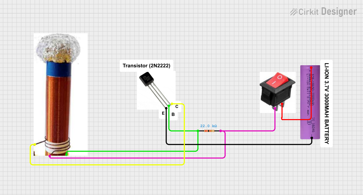

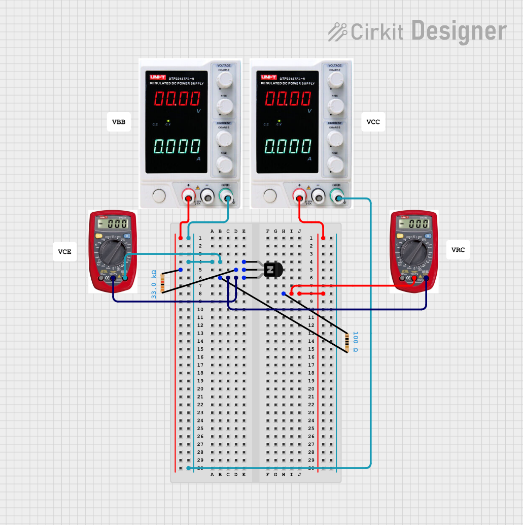
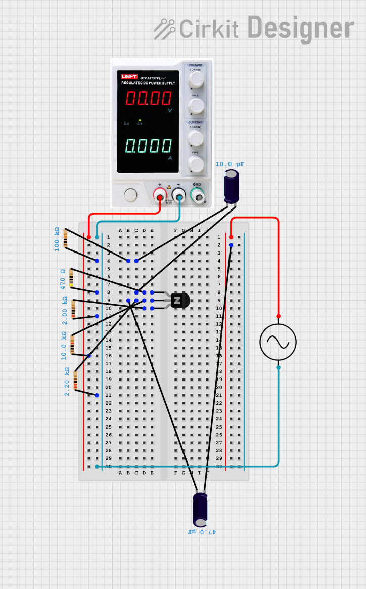
Explore Projects Built with 2N2222
Common Applications
- Signal amplification in audio and RF circuits
- Low-power switching applications
- Driving small relays, LEDs, or other loads
- Oscillator circuits
- General-purpose amplification in analog circuits
Technical Specifications
Below are the key technical details of the 2N2222 transistor:
| Parameter | Value |
|---|---|
| Transistor Type | NPN |
| Maximum Collector Current (Ic) | 800 mA |
| Maximum Collector-Emitter Voltage (Vce) | 40 V |
| Maximum Collector-Base Voltage (Vcb) | 75 V |
| Maximum Emitter-Base Voltage (Veb) | 6 V |
| DC Current Gain (hFE) | 100 to 300 (typical) |
| Power Dissipation (Ptot) | 500 mW |
| Transition Frequency (ft) | 250 MHz |
| Package Type | TO-18 (metal can) or TO-92 (plastic) |
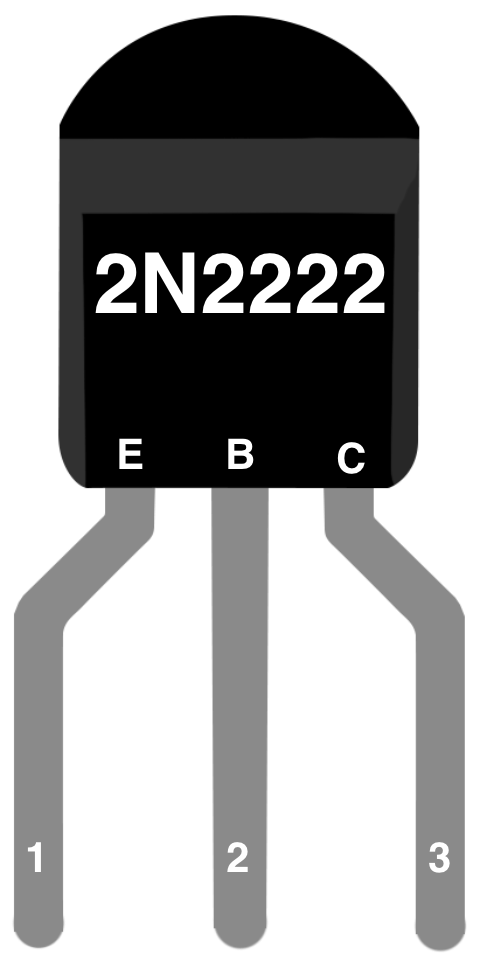
Pin Configuration
The 2N2222 is typically available in TO-18 or TO-92 packages. Below is the pin configuration for the TO-92 package:
| Pin Number | Pin Name | Description |
|---|---|---|
| 1 | Emitter | Connected to ground or the negative terminal of the circuit |
| 2 | Base | Controls the transistor's operation (input signal) |
| 3 | Collector | Connected to the load or positive terminal of the circuit |
Usage Instructions
Using the 2N2222 in a Circuit
- Determine the Configuration: Decide whether the transistor will be used as a switch or an amplifier.
- Switch: Apply a sufficient base current to turn the transistor fully on (saturation mode).
- Amplifier: Bias the transistor in the active region for linear operation.
- Base Resistor: Use a resistor in series with the base to limit the base current. Calculate the resistor value using Ohm's law: [ R_b = \frac{V_{in} - V_{be}}{I_b} ] where ( V_{in} ) is the input voltage, ( V_{be} ) is typically 0.7 V, and ( I_b ) is the desired base current.
- Collector Resistor: If used as an amplifier, connect a resistor to the collector to set the desired collector current.
- Power Ratings: Ensure the transistor operates within its maximum voltage, current, and power ratings to avoid damage.
Example: Controlling an LED with an Arduino UNO
The following example demonstrates how to use the 2N2222 to control an LED with an Arduino UNO:
Circuit Connections
- Emitter: Connect to ground.
- Base: Connect to an Arduino digital pin (via a 1 kΩ resistor).
- Collector: Connect to the negative terminal of the LED (with a 220 Ω resistor in series).
- LED Positive Terminal: Connect to the 5V pin of the Arduino.
Arduino Code
// Define the pin connected to the 2N2222 base
const int transistorBasePin = 9;

void setup() {
  // Set the transistor base pin as an output
  pinMode(transistorBasePin, OUTPUT);
}

void loop() {
  // Turn the LED on by sending a HIGH signal to the transistor base
  digitalWrite(transistorBasePin, HIGH);
  delay(1000); // Keep the LED on for 1 second

  // Turn the LED off by sending a LOW signal to the transistor base
  digitalWrite(transistorBasePin, LOW);
  delay(1000); // Keep the LED off for 1 second
}
Best Practices
- Always use a base resistor to prevent excessive current from damaging the transistor.
- Verify the power dissipation does not exceed 500 mW by calculating ( P = V_{ce} \times I_c ).
- Use a heat sink if the transistor operates near its maximum power rating for extended periods.
Troubleshooting and FAQs
Common Issues
Transistor Not Switching Properly
- Cause: Insufficient base current.
- Solution: Check the base resistor value and ensure the base current is at least ( I_c / h_{FE} ).
Overheating
- Cause: Exceeding power dissipation limits.
- Solution: Reduce the collector current or use a heat sink.
No Output Signal
- Cause: Incorrect pin connections.
- Solution: Double-check the emitter, base, and collector connections.
LED Not Turning On
- Cause: Incorrect resistor values or insufficient base drive.
- Solution: Verify the resistor values and ensure the Arduino pin outputs a HIGH signal.
FAQs
Q: Can the 2N2222 handle high-power loads?
A: No, the 2N2222 is designed for low to medium power applications. For high-power loads, consider using a power transistor like the TIP120.
Q: What is the maximum switching speed of the 2N2222?
A: The 2N2222 has a transition frequency (( f_t )) of 250 MHz, making it suitable for high-speed switching applications.
Q: Can I use the 2N2222 without a base resistor?
A: No, a base resistor is essential to limit the base current and prevent damage to the transistor.
By following this documentation, you can effectively use the 2N2222 transistor in your electronic projects!