Cirkit Designer Logo
Cirkit Designer
Your all-in-one circuit design IDE
Home / 
Component Documentation

How to Use Grove button: Examples, Pinouts, and Specs

Image of Grove button
Cirkit Designer LogoDesign with Grove button in Cirkit Designer

Introduction

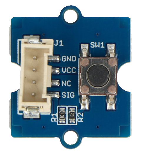
The Grove Button by Seeed Studio is a simple push-button switch designed for triggering events in electronic circuits. It is part of the Grove system, which simplifies prototyping and development by providing a plug-and-play interface for microcontrollers. The button is momentary, meaning it only remains active while being pressed, making it ideal for user input in various applications.

Explore Projects Built with Grove button

Use Cirkit Designer to design, explore, and prototype these projects online. Some projects support real-time simulation. Click "Open Project" to start designing instantly!
Pushbutton Interface with General Purpose I/O Plug
Image of Assista GP IO: A project utilizing Grove button in a practical application
This circuit consists of a General Purpose Input/Output (GPIO) plug connected to four pushbuttons. Each pushbutton is wired to a unique input pin on the GPIO plug, allowing the state of each button (pressed or not pressed) to be detected individually. The common terminals of the pushbuttons are interconnected and likely serve as a ground or reference voltage connection.
Cirkit Designer LogoOpen Project in Cirkit Designer
Arduino UNO Controlled LED with Pushbutton
Image of one green led & pull down: A project utilizing Grove button in a practical application
This circuit features an Arduino UNO configured to control a green LED using a pushbutton. The LED is connected to digital pin D13 through a 330 Ohm resistor, and the pushbutton is connected to digital pin D2 with a pull-down resistor to ground. When the button is pressed, the Arduino turns on the LED; when released, the LED turns off.
Cirkit Designer LogoOpen Project in Cirkit Designer
Arduino UNO Controlled Grove LED Bar Display
Image of Grove LED BAR: A project utilizing Grove button in a practical application
This circuit connects an Arduino UNO to a Grove LED bar. The Arduino provides power (5V and GND) to the LED bar and controls it using digital pins D6 and D7 for data input (DI) and clock input (DCKI), respectively. The provided code for the Arduino is a template with empty setup and loop functions, indicating that the specific functionality for controlling the LED bar has yet to be implemented.
Cirkit Designer LogoOpen Project in Cirkit Designer
Adafruit Circuit Playground-Based Interactive Control System with Pushbutton and Slide Potentiometers
Image of Lever Up Controller: A project utilizing Grove button in a practical application
This circuit features an Adafruit Circuit Playground Dev Edition microcontroller interfaced with a pushbutton and two slide potentiometers. The pushbutton is connected to digital pin D6, while the potentiometers provide analog input to pins D9 and D10, allowing for variable control inputs.
Cirkit Designer LogoOpen Project in Cirkit Designer

Explore Projects Built with Grove button

Use Cirkit Designer to design, explore, and prototype these projects online. Some projects support real-time simulation. Click "Open Project" to start designing instantly!
Image of Assista GP IO: A project utilizing Grove button in a practical application
Pushbutton Interface with General Purpose I/O Plug
This circuit consists of a General Purpose Input/Output (GPIO) plug connected to four pushbuttons. Each pushbutton is wired to a unique input pin on the GPIO plug, allowing the state of each button (pressed or not pressed) to be detected individually. The common terminals of the pushbuttons are interconnected and likely serve as a ground or reference voltage connection.
Cirkit Designer LogoOpen Project in Cirkit Designer
Image of one green led & pull down: A project utilizing Grove button in a practical application
Arduino UNO Controlled LED with Pushbutton
This circuit features an Arduino UNO configured to control a green LED using a pushbutton. The LED is connected to digital pin D13 through a 330 Ohm resistor, and the pushbutton is connected to digital pin D2 with a pull-down resistor to ground. When the button is pressed, the Arduino turns on the LED; when released, the LED turns off.
Cirkit Designer LogoOpen Project in Cirkit Designer
Image of Grove LED BAR: A project utilizing Grove button in a practical application
Arduino UNO Controlled Grove LED Bar Display
This circuit connects an Arduino UNO to a Grove LED bar. The Arduino provides power (5V and GND) to the LED bar and controls it using digital pins D6 and D7 for data input (DI) and clock input (DCKI), respectively. The provided code for the Arduino is a template with empty setup and loop functions, indicating that the specific functionality for controlling the LED bar has yet to be implemented.
Cirkit Designer LogoOpen Project in Cirkit Designer
Image of Lever Up Controller: A project utilizing Grove button in a practical application
Adafruit Circuit Playground-Based Interactive Control System with Pushbutton and Slide Potentiometers
This circuit features an Adafruit Circuit Playground Dev Edition microcontroller interfaced with a pushbutton and two slide potentiometers. The pushbutton is connected to digital pin D6, while the potentiometers provide analog input to pins D9 and D10, allowing for variable control inputs.
Cirkit Designer LogoOpen Project in Cirkit Designer

Common Applications

  • User input for microcontroller-based projects
  • Triggering events in IoT devices
  • Reset or start buttons in embedded systems
  • Educational projects and prototyping

Technical Specifications

The Grove Button is designed for ease of use and compatibility with the Grove ecosystem. Below are its key technical details:

Parameter Value
Operating Voltage 3.3V / 5V
Operating Current ≤10 mA
Interface Type Grove 4-pin connector
Button Type Momentary (push-to-make)
Dimensions 20mm x 20mm
Weight 3g

Pin Configuration and Descriptions

The Grove Button uses a standard 4-pin Grove connector. The pinout is as follows:

Pin Name Description
1 GND Ground pin
2 VCC Power supply pin (3.3V or 5V)
3 SIG Signal pin (outputs HIGH when button is pressed)
4 NC Not connected

Usage Instructions

The Grove Button is straightforward to use and can be connected directly to a microcontroller, such as an Arduino UNO, using the Grove Base Shield. Below are the steps to integrate and use the button in a circuit:

Connecting the Grove Button

  1. Attach the Grove Button to a Grove Base Shield using a 4-pin Grove cable.
  2. Connect the Base Shield to your microcontroller (e.g., Arduino UNO).
  3. Ensure the microcontroller is powered with a compatible voltage (3.3V or 5V).

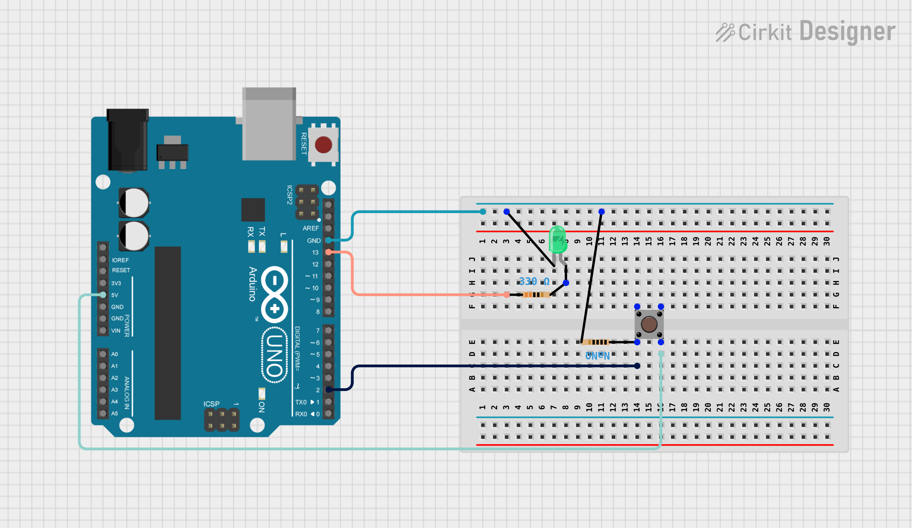
Example Arduino Code

The following example demonstrates how to use the Grove Button with an Arduino UNO. When the button is pressed, the onboard LED (connected to pin 13) will turn on.

// Define the pin connected to the Grove Button
const int buttonPin = 2;  // Signal pin of the Grove Button
const int ledPin = 13;    // Onboard LED pin

void setup() {
  pinMode(buttonPin, INPUT);  // Set the button pin as input
  pinMode(ledPin, OUTPUT);   // Set the LED pin as output
}

void loop() {
  int buttonState = digitalRead(buttonPin);  // Read the button state

  if (buttonState == HIGH) {
    // If the button is pressed, turn on the LED
    digitalWrite(ledPin, HIGH);
  } else {
    // If the button is not pressed, turn off the LED
    digitalWrite(ledPin, LOW);
  }
}

Important Considerations

  • Debouncing: Mechanical buttons like the Grove Button may produce noise or "bouncing" when pressed. For applications requiring precise input, consider implementing software debouncing.
  • Voltage Compatibility: Ensure the microcontroller operates at 3.3V or 5V to match the Grove Button's specifications.
  • Signal Pin Behavior: The signal pin outputs a HIGH (logic 1) when the button is pressed and LOW (logic 0) when released.

Troubleshooting and FAQs

Common Issues

  1. Button Not Responding

    • Cause: Loose connection or incorrect wiring.
    • Solution: Verify that the Grove cable is securely connected to both the button and the Base Shield. Check the pin assignments in your code.
  2. Button Always Reads HIGH

    • Cause: Floating input pin or incorrect pull-up configuration.
    • Solution: Ensure the button pin is properly configured as an input in the code. The Grove Button has an internal pull-up resistor, so no external pull-up is needed.
  3. Button Presses Are Inconsistent

    • Cause: Button bouncing.
    • Solution: Implement a software debounce routine to filter out noise from the button press.

FAQs

Q: Can I use the Grove Button without a Grove Base Shield?
A: Yes, you can connect the button directly to a microcontroller using jumper wires. However, ensure you correctly map the pins (GND, VCC, SIG) to the microcontroller.

Q: Is the Grove Button compatible with Raspberry Pi?
A: Yes, the Grove Button can be used with Raspberry Pi via the Grove Pi+ or by directly connecting the pins to the GPIO header.

Q: Does the button support analog input?
A: No, the Grove Button is a digital input device and outputs either HIGH or LOW signals.

Q: Can I use multiple Grove Buttons in a single project?
A: Yes, you can connect multiple Grove Buttons to different digital pins on your microcontroller. Ensure each button is assigned a unique pin in your code.