How to Use Raspberry Pi: Examples, Pinouts, and Specs
Introduction
The Raspberry Pi, manufactured by 123, is a small, affordable single-board computer designed for a wide range of applications. It is particularly popular in programming, electronics, and Internet of Things (IoT) projects. With its compact size and powerful capabilities, the Raspberry Pi is an excellent tool for hobbyists, educators, and professionals alike.
Common applications of the Raspberry Pi include:
- Learning programming languages such as Python, Java, and C.
- Building IoT devices and smart home systems.
- Prototyping electronics projects.
- Running lightweight servers or media centers.
- Robotics and automation projects.
Explore Projects Built with Raspberry Pi
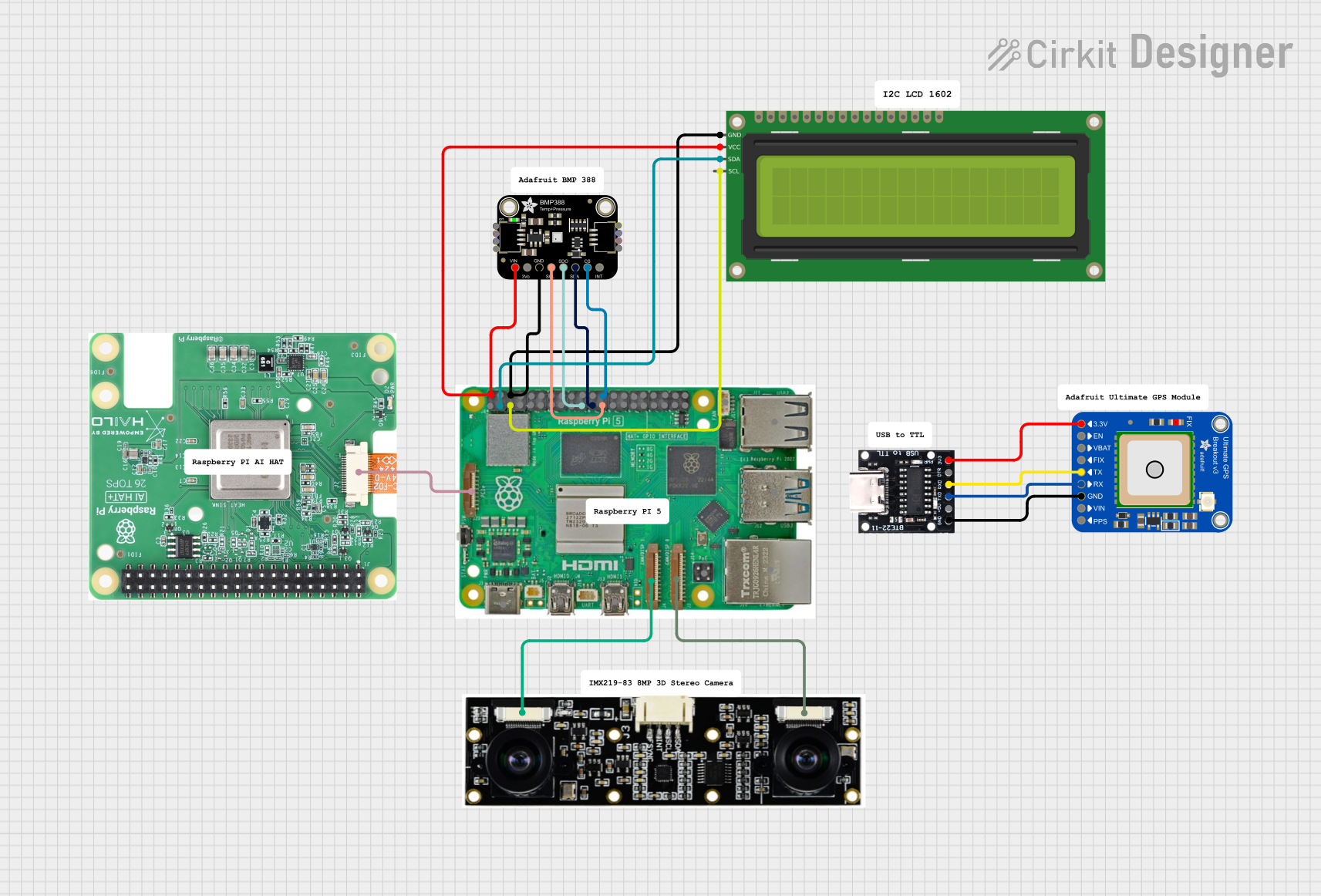
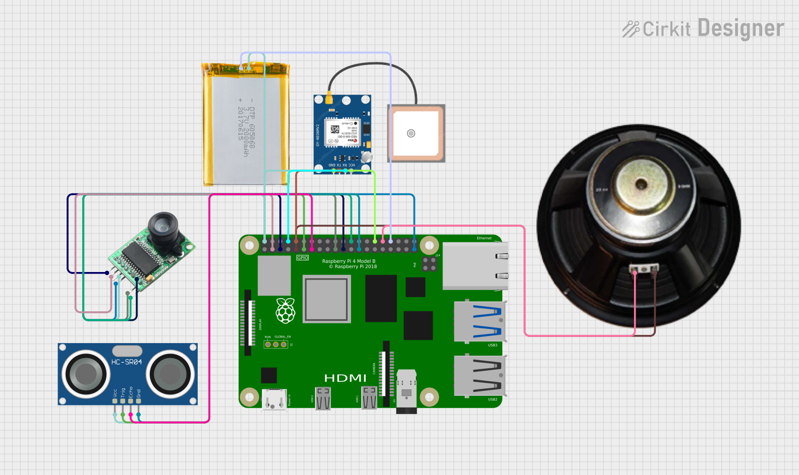
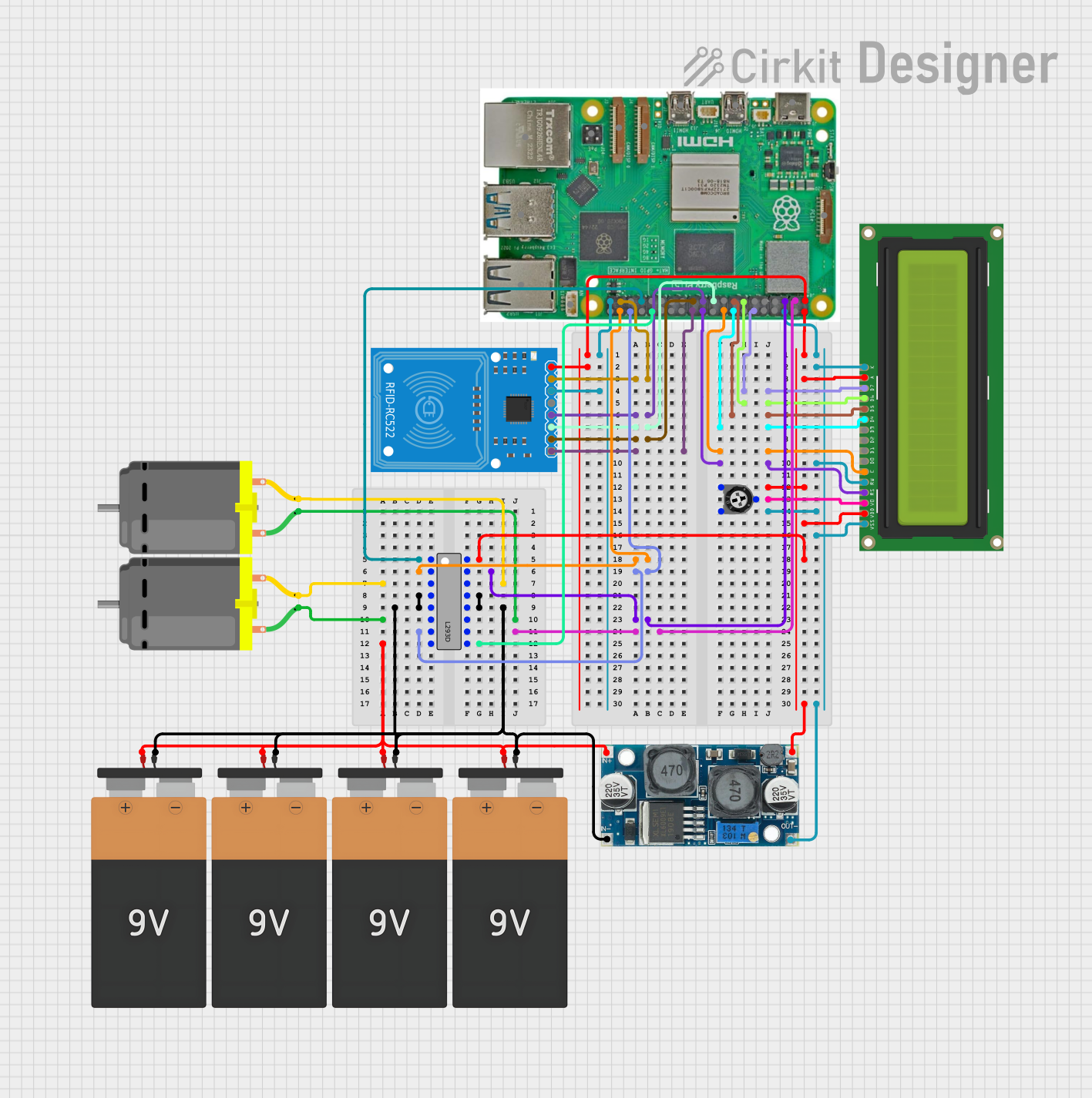

Explore Projects Built with Raspberry Pi
Technical Specifications
Below are the key technical details for the Raspberry Pi:
| Specification | Details |
|---|---|
| Manufacturer | 123 |
| Part ID | 123 |
| Processor | Quad-core ARM Cortex-A series processor (varies by model) |
| RAM | 512MB to 8GB (depending on the model) |
| Storage | MicroSD card slot for storage and operating system |
| Connectivity | Wi-Fi, Bluetooth, Ethernet (varies by model) |
| GPIO Pins | 40-pin GPIO header for interfacing with external components |
| Power Supply | 5V/3A via USB-C or micro-USB (depending on the model) |
| Video Output | HDMI or micro-HDMI (supports up to 4K resolution on newer models) |
| USB Ports | USB 2.0 and USB 3.0 ports (varies by model) |
| Operating System | Raspberry Pi OS (Linux-based) or other compatible operating systems |
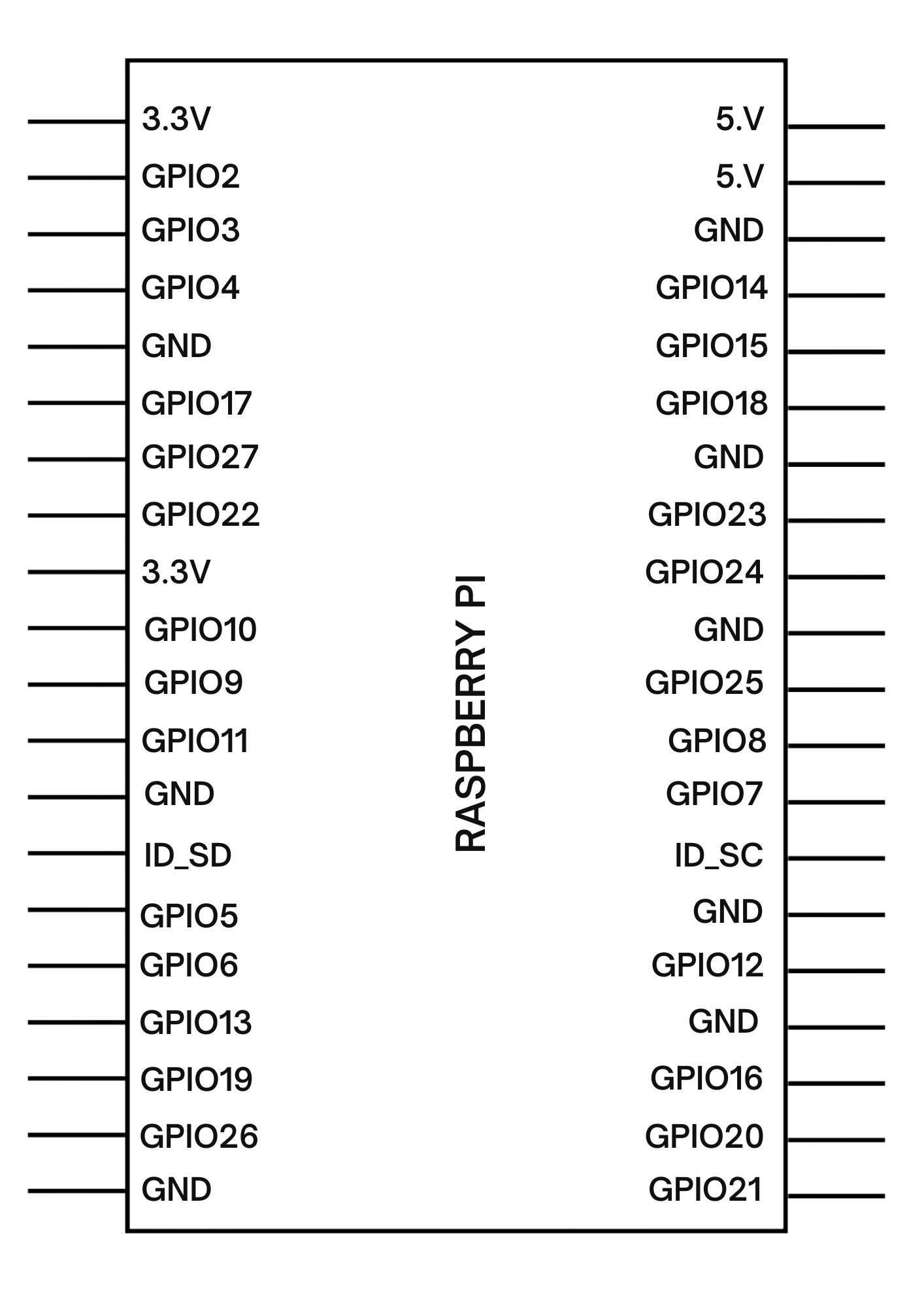
GPIO Pin Configuration
The Raspberry Pi features a 40-pin General Purpose Input/Output (GPIO) header. Below is a table summarizing the pin configuration:
| Pin Number | Pin Name | Description |
|---|---|---|
| 1 | 3.3V Power | Provides 3.3V power output |
| 2 | 5V Power | Provides 5V power output |
| 3 | GPIO2 (SDA1) | I2C Data |
| 4 | 5V Power | Provides 5V power output |
| 5 | GPIO3 (SCL1) | I2C Clock |
| 6 | Ground | Ground |
| 7 | GPIO4 | General-purpose I/O |
| 8 | GPIO14 (TXD) | UART Transmit |
| 9 | Ground | Ground |
| 10 | GPIO15 (RXD) | UART Receive |
| ... | ... | ... |
| 39 | Ground | Ground |
| 40 | GPIO21 | General-purpose I/O |
For the full GPIO pinout, refer to the official Raspberry Pi documentation.
Usage Instructions
How to Use the Raspberry Pi in a Circuit
- Powering the Raspberry Pi: Use a 5V/3A power supply via the USB-C or micro-USB port. Ensure the power supply meets the required specifications to avoid instability.
- Connecting Peripherals: Attach a monitor via HDMI, a keyboard and mouse via USB, and a microSD card with the operating system installed.
- Using GPIO Pins: Connect external components (e.g., LEDs, sensors) to the GPIO pins. Use appropriate resistors and circuits to prevent damage to the Raspberry Pi.
- Programming: Write and execute code using programming languages like Python. The Raspberry Pi OS includes tools like Thonny IDE for Python development.
Important Considerations and Best Practices
- Always shut down the Raspberry Pi properly before disconnecting power to avoid corrupting the microSD card.
- Use a heatsink or fan for cooling if running resource-intensive applications.
- Avoid connecting components directly to the GPIO pins without proper resistors or level shifters to prevent damage.
- Regularly update the operating system and software to ensure security and performance.
Example: Blinking an LED with Raspberry Pi
Below is an example of how to blink an LED using the Raspberry Pi and Python:
Import the GPIO library and time module
import RPi.GPIO as GPIO import time
Set the GPIO mode to BCM (Broadcom pin numbering)
GPIO.setmode(GPIO.BCM)
Define the GPIO pin connected to the LED
LED_PIN = 18
Set up the LED pin as an output
GPIO.setup(LED_PIN, GPIO.OUT)
try: while True: GPIO.output(LED_PIN, GPIO.HIGH) # Turn the LED on time.sleep(1) # Wait for 1 second GPIO.output(LED_PIN, GPIO.LOW) # Turn the LED off time.sleep(1) # Wait for 1 second except KeyboardInterrupt: # Clean up GPIO settings when the program is interrupted GPIO.cleanup()
**Note**: Connect the LED to GPIO18 with a 330-ohm resistor in series to limit current.
Troubleshooting and FAQs
Common Issues
Raspberry Pi Does Not Boot:
- Ensure the microSD card is properly inserted and contains a valid operating system.
- Check the power supply for sufficient voltage and current.
No Display on Monitor:
- Verify the HDMI cable is securely connected.
- Ensure the monitor is powered on and set to the correct input source.
GPIO Pins Not Working:
- Double-check the pin connections and ensure the correct GPIO numbering is used in the code.
- Ensure the GPIO pins are not damaged or shorted.
Overheating:
- Use a heatsink or fan to cool the Raspberry Pi.
- Avoid running resource-intensive applications for extended periods without proper cooling.
Tips for Troubleshooting
- Use the
dmesgcommand in the terminal to check for system errors. - Test the GPIO pins with a multimeter to ensure they are functioning correctly.
- Refer to the official Raspberry Pi forums and documentation for additional support.
By following this documentation, users can effectively utilize the Raspberry Pi for a variety of projects and applications.