How to Use SparkFun Spectrum Shield: Examples, Pinouts, and Specs
Introduction
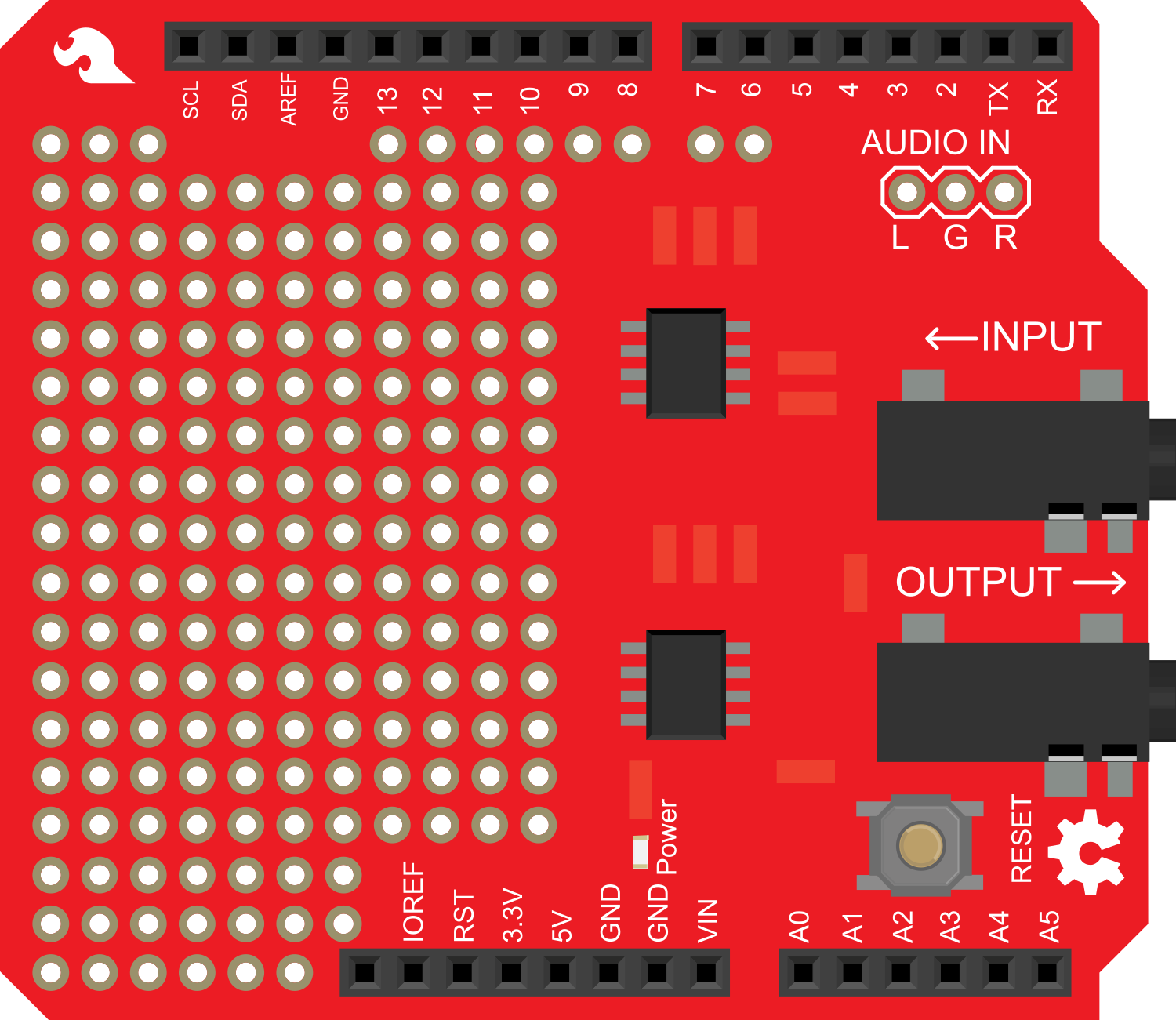
The SparkFun Spectrum Shield is an innovative board designed for sound analysis and visualization. It enables users to input audio signals and outputs a visual representation of the frequency spectrum. This shield is commonly used in projects that require audio signal processing, such as creating visual effects in response to music, building graphic equalizers, or for educational purposes to demonstrate how sound frequencies can be analyzed and displayed.
Explore Projects Built with SparkFun Spectrum Shield
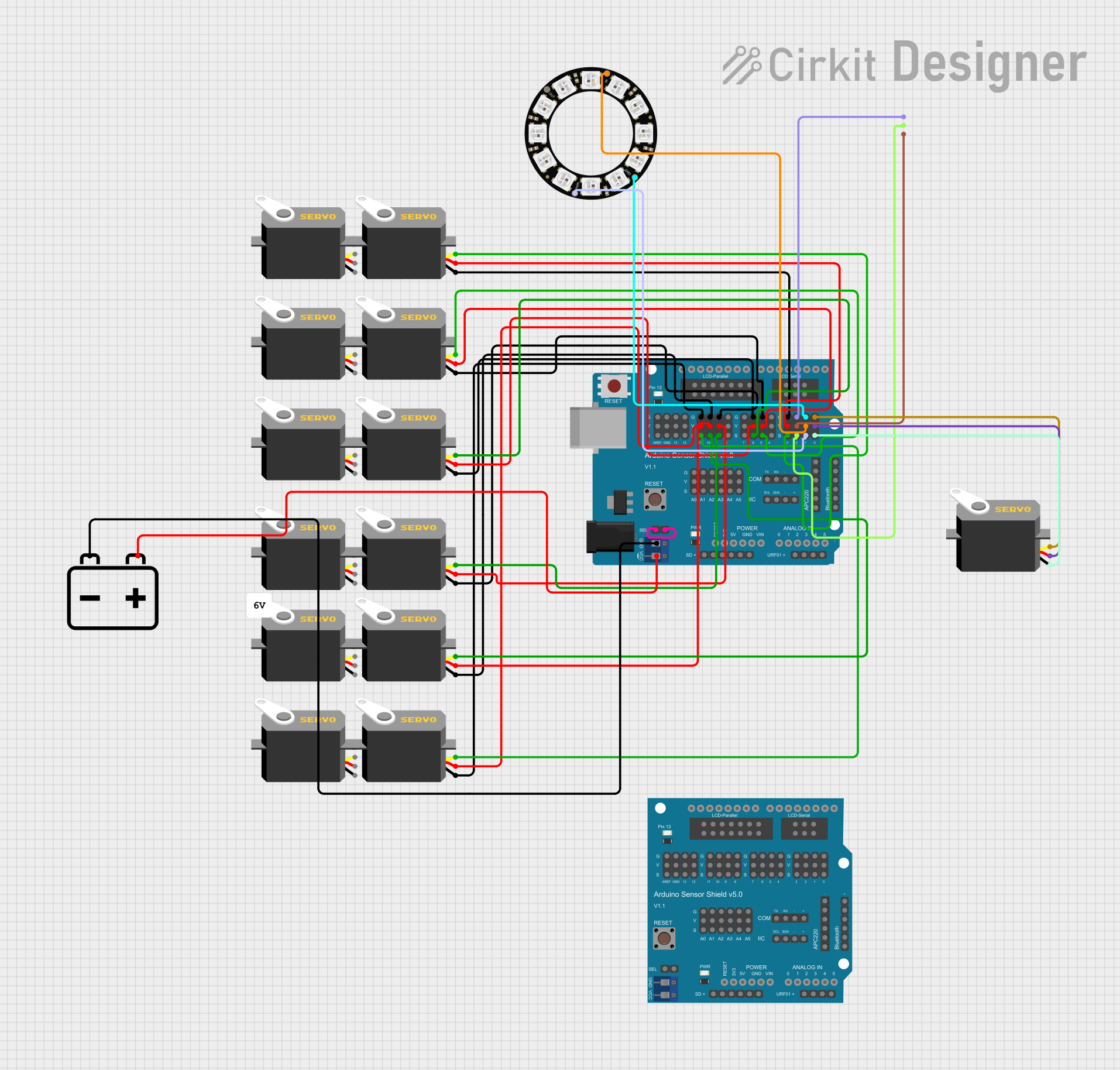

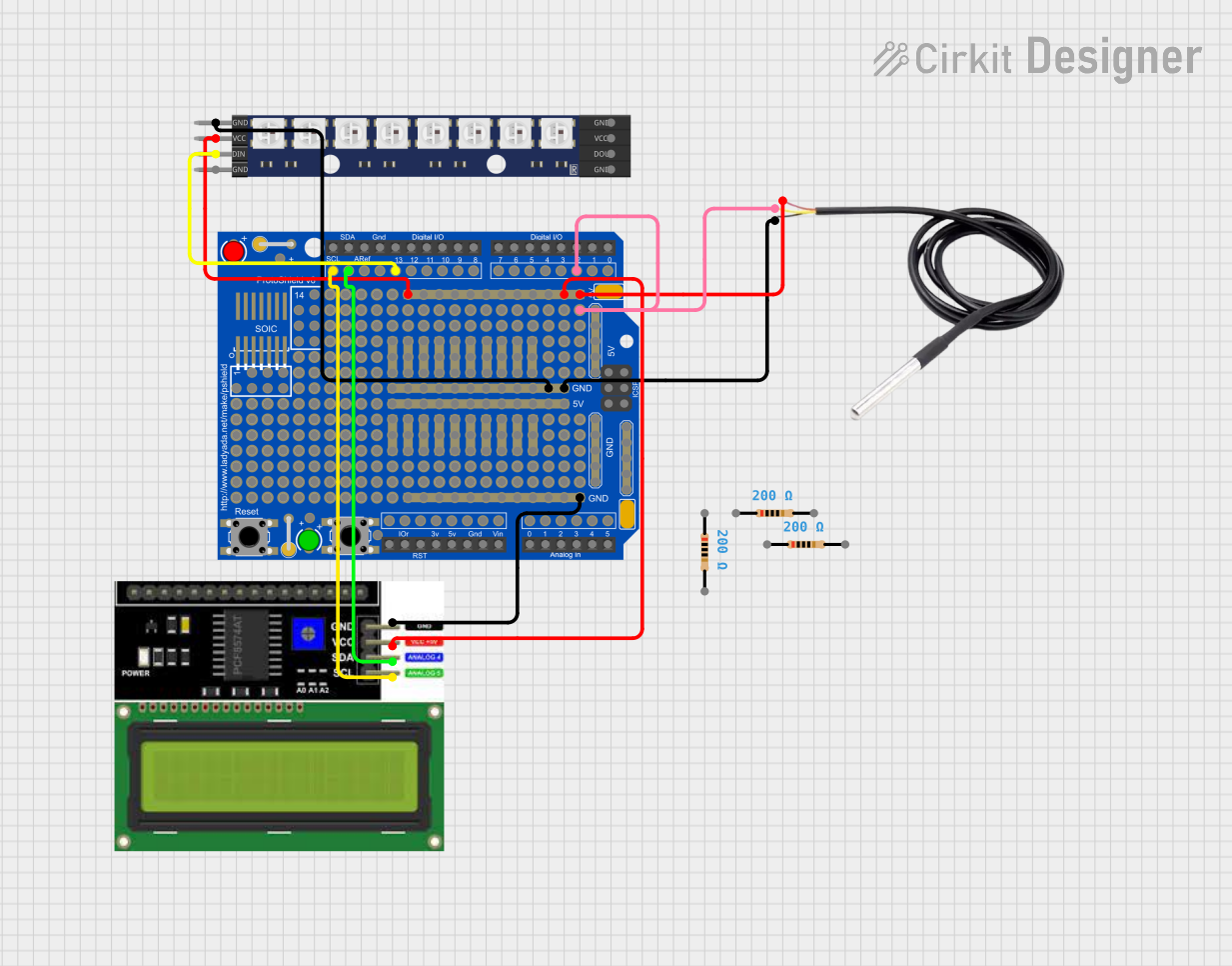
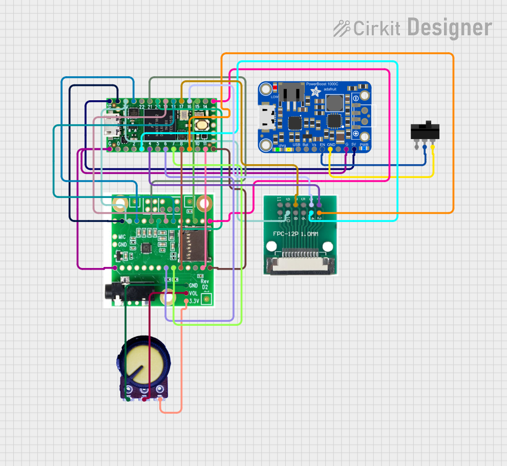
Explore Projects Built with SparkFun Spectrum Shield
Common Applications and Use Cases
- Music visualizers
- Audio-responsive LED displays
- Graphic equalizers
- Educational tools for sound analysis
- Sound-based interactive installations
Technical Specifications
Key Technical Details
- Operating Voltage: 3.3V to 5V
- Frequency Range: 63Hz to 16kHz
- Channels: Two channels (stereo)
- Resolution: 7 bands per channel
- ICs Used: Two MSGEQ7 graphic equalizer display filters
Pin Configuration and Descriptions
| Pin Number | Function | Description |
|---|---|---|
| A0 | Strobe | Controls the multiplexing of the MSGEQ7 ICs |
| A1 | Reset | Resets the multiplexing process |
| A2 | Left Audio Out | Outputs the frequency analysis of the left audio channel |
| A3 | Right Audio Out | Outputs the frequency analysis of the right audio channel |
| A4 | Left Audio In | Inputs the left channel audio signal |
| A5 | Right Audio In | Inputs the right channel audio signal |
| 5V | Power | Supplies power to the shield |
| GND | Ground | Common ground reference |
Usage Instructions
How to Use the Component in a Circuit
- Powering the Shield: Connect the 5V and GND pins to the corresponding power supply pins on your Arduino UNO.
- Inputting Audio: Connect the audio source to the Left Audio In and Right Audio In pins. This can be done using a 3.5mm audio jack or directly soldering wires.
- Outputting Frequency Data: Connect the Left Audio Out and Right Audio Out pins to the analog input pins on your Arduino UNO for further processing or visualization.
- Controlling the MSGEQ7 ICs: Connect the Strobe and Reset pins to digital pins on your Arduino UNO.
Important Considerations and Best Practices
- Ensure that the audio source level is appropriate for the input pins to avoid signal distortion.
- Use capacitors for power supply filtering if you encounter noise in the audio signal.
- Keep the audio signal wires as short as possible to minimize interference.
- Avoid placing the shield near strong electromagnetic fields to prevent interference.
Example Arduino Code
#include <Arduino.h>

// Define the pin connections
const int strobePin = 2; // Connect to pin A0 on the shield
const int resetPin = 3;  // Connect to pin A1 on the shield
const int spectrumPins[] = {A2, A3}; // Connect to pins A2 and A3 on the shield

void setup() {
  // Set up the communication pins
  pinMode(strobePin, OUTPUT);
  pinMode(resetPin, OUTPUT);
  digitalWrite(resetPin, LOW);
  digitalWrite(strobePin, HIGH);

  // Set up the spectrum pins
  for (int i = 0; i < 2; i++) {
    pinMode(spectrumPins[i], INPUT);
  }

  // Begin serial communication for debugging
  Serial.begin(9600);
}

void loop() {
  // Reset the MSGEQ7 before reading the frequency bands
  digitalWrite(resetPin, HIGH);
  digitalWrite(resetPin, LOW);

  for (int i = 0; i < 7; i++) {
    digitalWrite(strobePin, LOW);
    delayMicroseconds(30); // Allow the MSGEQ7's output to settle
    // Read the frequency band amplitude from both channels
    int leftChannel = analogRead(spectrumPins[0]);
    int rightChannel = analogRead(spectrumPins[1]);
    digitalWrite(strobePin, HIGH);

    // Print the results to the serial monitor
    Serial.print("Band ");
    Serial.print(i);
    Serial.print(": Left=");
    Serial.print(leftChannel);
    Serial.print(" Right=");
    Serial.println(rightChannel);
  }

  // Delay before the next reading
  delay(50);
}
Troubleshooting and FAQs
Common Issues Users Might Face
- No Output on Serial Monitor: Ensure that the Arduino is correctly connected to the computer and that the correct COM port is selected in the Arduino IDE.
- Distorted Audio Signal: Check the audio source level and ensure it's not too high for the input pins. Adjust the volume or use a potentiometer to attenuate the signal if necessary.
- Inconsistent Frequency Data: Ensure that the strobe and reset sequences are correctly implemented in the code. Also, check for any loose connections.
Solutions and Tips for Troubleshooting
- If you encounter noise in the frequency data, try adding a 0.1uF capacitor between the power and ground pins of the shield.
- Use shielded cables for audio input to reduce the chance of picking up electromagnetic interference.
- If the LEDs or display connected to the output pins do not behave as expected, verify that the pins are correctly mapped in your code.
FAQs
Q: Can I use the Spectrum Shield with a 3.3V system? A: Yes, the Spectrum Shield can operate at 3.3V, but ensure that the audio signal levels are compatible.
Q: How can I connect multiple Spectrum Shields to an Arduino? A: You can connect multiple shields in parallel, but you will need to manage the strobe and reset lines separately for each shield to avoid interference.
Q: What is the purpose of the MSGEQ7 IC on the shield? A: The MSGEQ7 IC is a graphic equalizer display filter that splits the audio signal into seven frequency bands, making it easier to visualize the spectrum.
Q: Can I use the Spectrum Shield without an Arduino? A: While the shield is designed for use with an Arduino, it can be used with any microcontroller that has the necessary analog and digital I/O pins. Adjustments to the code and connections may be required.