How to Use Adafruit 14-segment LED Alphanumeric Backpack Blue: Examples, Pinouts, and Specs
Introduction
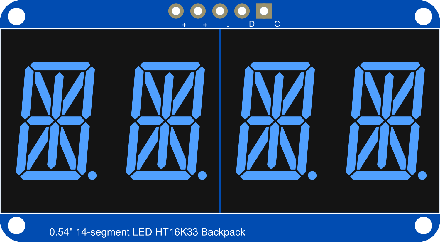
The Adafruit 14-Segment LED Alphanumeric Backpack is a versatile and visually appealing display module that allows users to add a bright, easy-to-read display to their projects. This blue LED display is capable of showing letters, numbers, and a variety of characters by illuminating specific combinations of its 14 segments. Common applications include digital clocks, counters, and readouts for various sensors in hobbyist and educational projects.
Explore Projects Built with Adafruit 14-segment LED Alphanumeric Backpack Blue
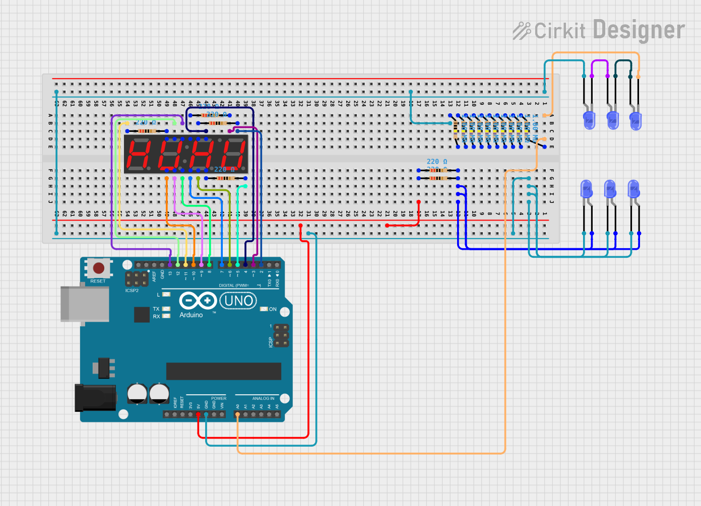
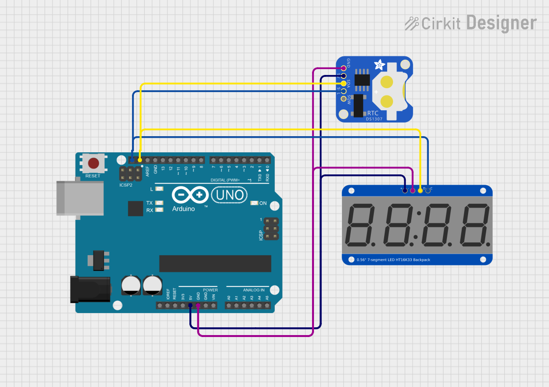

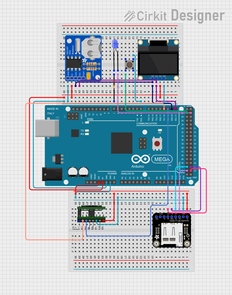
Explore Projects Built with Adafruit 14-segment LED Alphanumeric Backpack Blue
Technical Specifications
Key Technical Details
- Display Color: Blue
- LED Type: Alphanumeric, 14-segment
- Operating Voltage: 2.3V to 5.5V
- Max Current (per segment): 30 mA
- Interface: I2C
- I2C Addresses: 0x70 (default) - 0x77 (selectable with solder jumpers)
- Dimensions: 1.2" x 1.5" (without headers)
Pin Configuration and Descriptions
| Pin Name | Description |
|---|---|
| VCC | Power supply (2.3V to 5.5V) |
| GND | Ground |
| SDA | I2C Data Line |
| SCL | I2C Clock Line |
| ADDR | Address selection (connect to GND or VCC) |
| RST | Reset pin (optional, connect to VCC if unused) |
Usage Instructions
Integration with a Circuit
To use the Adafruit 14-Segment LED Alphanumeric Backpack in a circuit, follow these steps:
- Connect the VCC pin to the power supply (2.3V to 5.5V).
- Connect the GND pin to the ground of the power supply.
- Connect the SDA and SCL pins to the I2C data and clock lines, respectively.
- If using multiple displays, set unique I2C addresses using the ADDR pins.
- Optionally, connect the RST pin to a digital output on your microcontroller if you wish to control the reset function programmatically.
Best Practices
- Use a current-limiting resistor if operating at a voltage significantly higher than 2.3V to prevent damage to the LEDs.
- Ensure that the I2C bus has pull-up resistors, as they are typically not included on the LED backpack.
- Avoid exposing the display to mechanical stress or extreme temperatures.
Example Code for Arduino UNO
#include <Wire.h>
#include <Adafruit_GFX.h>
#include <Adafruit_LEDBackpack.h>

Adafruit_AlphaNum4 display = Adafruit_AlphaNum4();

void setup() {
  display.begin(0x70);  // Initialize the display with its I2C address
  display.setBrightness(15);  // Set the display brightness (0-15)
  display.writeDisplay();  // Write data to the display
}

void loop() {
  display.clear();  // Clear the display buffer
  display.writeDigitAscii(0, 'H');  // Set 'H' on the first digit
  display.writeDigitAscii(1, 'E');  // Set 'E' on the second digit
  display.writeDigitAscii(2, 'L');  // Set 'L' on the third digit
  display.writeDigitAscii(3, 'P');  // Set 'P' on the fourth digit
  display.writeDisplay();  // Send buffer to the display
  delay(1000);  // Wait for a second
}
Troubleshooting and FAQs
Common Issues
- Display Not Lighting Up: Ensure that the power supply is connected correctly and within the specified voltage range. Check the I2C connections and address settings.
- Characters Not Displaying Correctly: Verify that the correct character mapping is used in your code. Ensure that the display is not damaged.
- Dim Display: Adjust the brightness setting in your code or check the power supply voltage.
FAQs
Q: Can I daisy-chain multiple displays? A: Yes, you can connect multiple displays in series by connecting the SDA and SCL lines together and setting unique I2C addresses for each display.
Q: How do I change the I2C address? A: The I2C address can be changed by soldering the address jumpers on the back of the PCB to connect them to either VCC or GND.
Q: What is the maximum number of characters that can be displayed? A: The backpack supports up to four characters at a time. However, multiple backpacks can be chained together for longer messages.
Q: Can the display show special characters? A: Yes, the display can show a variety of special characters and symbols by lighting up the appropriate segments. You may need to create custom character maps for less common symbols.
For further assistance, consult the Adafruit support forums or the product's official documentation.