How to Use Adafruit TMC2209: Examples, Pinouts, and Specs
Introduction
The Adafruit TMC2209 is a high-performance stepper motor driver designed for smooth, quiet, and efficient operation. It features advanced capabilities such as microstepping, stall detection, and UART communication for easy configuration and control. This driver is ideal for applications requiring precise motor control, such as 3D printers, CNC machines, and robotics.
Explore Projects Built with Adafruit TMC2209

Explore Projects Built with Adafruit TMC2209
Common Applications and Use Cases
- 3D printers for precise and quiet motor control
- CNC machines for high-accuracy positioning
- Robotics for smooth and efficient motion
- Automated systems requiring low-noise stepper motor operation
Technical Specifications
The Adafruit TMC2209 offers a range of features and specifications that make it a versatile and powerful stepper motor driver.
Key Technical Details
- Input Voltage Range: 4.75V to 29V
- Maximum Motor Current: 2.0A RMS (2.8A peak)
- Microstepping: Up to 1/256 steps
- Communication Interface: UART for advanced configuration
- Stall Detection: Integrated StallGuard™ for sensorless homing
- CoolStep™ Technology: Adaptive current control for energy efficiency
- Operating Temperature: -40°C to +125°C
- Dimensions: 20mm x 15mm (approx.)
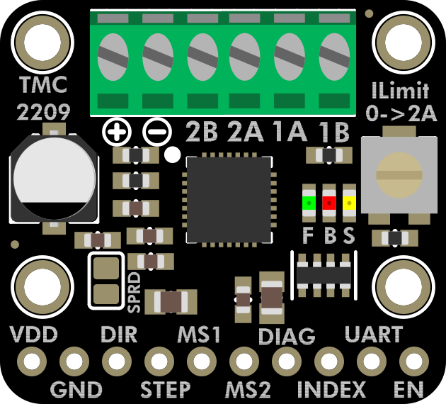
Pin Configuration and Descriptions
The TMC2209 module has several pins for power, motor control, and communication. Below is the pinout and description:
| Pin Name | Description |
|---|---|
| VM | Motor power supply input (4.75V to 29V). |
| GND | Ground connection. |
| VIO | Logic voltage input (typically 3.3V or 5V). |
| EN | Enable pin (active low). |
| DIR | Direction control input. |
| STEP | Step pulse input for motor movement. |
| UART_TX | UART transmit pin for communication. |
| UART_RX | UART receive pin for communication. |
| MS1, MS2 | Microstepping resolution selection pins. |
| DIAG | Diagnostic output for stall detection and other status signals. |
| A1, A2 | Motor coil A connections. |
| B1, B2 | Motor coil B connections. |
Usage Instructions
The Adafruit TMC2209 is straightforward to use in a circuit, but proper setup is essential for optimal performance.
How to Use the Component in a Circuit
- Power Supply: Connect the VM pin to a power supply within the range of 4.75V to 29V. Ensure the power supply can handle the current requirements of your stepper motor.
- Logic Voltage: Connect the VIO pin to the logic voltage of your microcontroller (e.g., 3.3V or 5V).
- Motor Connections: Connect the stepper motor coils to the A1, A2, B1, and B2 pins. Ensure the wiring matches the motor's datasheet.
- Control Pins: Connect the STEP and DIR pins to your microcontroller for step and direction control.
- UART Communication (Optional): Connect the UART_TX and UART_RX pins to your microcontroller for advanced configuration and monitoring.
- Microstepping: Use the MS1 and MS2 pins to set the desired microstepping resolution. Refer to the TMC2209 datasheet for the microstepping table.
Important Considerations and Best Practices
- Cooling: The TMC2209 can generate heat during operation. Use a heatsink or active cooling if necessary.
- Current Limiting: Set the motor current limit using the onboard potentiometer or via UART to prevent overheating and damage.
- Stall Detection: Enable StallGuard™ for sensorless homing and stall detection. This requires UART configuration.
- Decoupling Capacitors: Place decoupling capacitors close to the VM and VIO pins to reduce noise and ensure stable operation.
Example Code for Arduino UNO
Below is an example of how to control the TMC2209 with an Arduino UNO using basic step and direction signals:
// Define pin connections
#define STEP_PIN 3  // Pin connected to STEP
#define DIR_PIN 4   // Pin connected to DIR

void setup() {
  pinMode(STEP_PIN, OUTPUT); // Set STEP pin as output
  pinMode(DIR_PIN, OUTPUT);  // Set DIR pin as output

  digitalWrite(DIR_PIN, LOW); // Set initial direction (LOW = one direction)
}

void loop() {
  // Generate step pulses
  digitalWrite(STEP_PIN, HIGH); // Set STEP pin HIGH
  delayMicroseconds(500);       // Wait 500 microseconds
  digitalWrite(STEP_PIN, LOW);  // Set STEP pin LOW
  delayMicroseconds(500);       // Wait 500 microseconds
}
This code generates step pulses to move the motor. Adjust the delayMicroseconds values to control the motor speed.
Troubleshooting and FAQs
Common Issues and Solutions
Motor Not Moving:
- Check the power supply voltage and current rating.
- Verify the motor connections (A1, A2, B1, B2).
- Ensure the STEP and DIR signals are being sent correctly.
Overheating:
- Reduce the motor current limit using the potentiometer or UART.
- Add a heatsink or active cooling to the driver.
Stall Detection Not Working:
- Ensure UART communication is properly configured.
- Verify that StallGuard™ is enabled in the driver settings.
Noisy Operation:
- Check the microstepping settings (MS1, MS2).
- Use decoupling capacitors to reduce electrical noise.
FAQs
Q: Can I use the TMC2209 with a 12V power supply?
A: Yes, the TMC2209 supports input voltages from 4.75V to 29V, so a 12V power supply is within the supported range.
Q: How do I enable UART communication?
A: Connect the UART_TX and UART_RX pins to your microcontroller and configure the UART settings in your firmware. Libraries like TMCStepper for Arduino can simplify this process.
Q: What is the maximum microstepping resolution?
A: The TMC2209 supports up to 1/256 microstepping for extremely smooth motor operation.
Q: Do I need external resistors for the MS1 and MS2 pins?
A: No, the MS1 and MS2 pins have internal pull-up or pull-down resistors. However, you can override these with external connections if needed.
By following this documentation, you can effectively integrate the Adafruit TMC2209 into your projects for precise and quiet stepper motor control.