Cirkit Designer Logo
Cirkit Designer
Your all-in-one circuit design IDE
Home / 
Component Documentation

How to Use Turbidity Module: Examples, Pinouts, and Specs

Image of Turbidity Module
Cirkit Designer LogoDesign with Turbidity Module in Cirkit Designer

Introduction

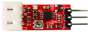
A Turbidity Module is an electronic sensor designed to measure the turbidity, or cloudiness, of a liquid. Turbidity is an important parameter in assessing water quality, as it can indicate the presence of pollutants, suspended solids, and microorganisms. This sensor is commonly used in environmental monitoring, water treatment, and laboratory analysis to ensure safe drinking water and to monitor the health of aquatic ecosystems.

Explore Projects Built with Turbidity Module

Use Cirkit Designer to design, explore, and prototype these projects online. Some projects support real-time simulation. Click "Open Project" to start designing instantly!
Arduino UNO-Based Turbidity Sensor Module for Water Quality Monitoring
Image of SensorTurb: A project utilizing Turbidity Module in a practical application
This circuit uses an Arduino UNO to read data from a turbidity module, which measures the cloudiness of a liquid. The turbidity module is powered by the Arduino's 5V and GND pins, and its output is connected to the Arduino's analog input pin A0 for data acquisition.
Cirkit Designer LogoOpen Project in Cirkit Designer
Arduino GIGA R1 WIFI Turbidity Monitoring System
Image of TurbidShower: A project utilizing Turbidity Module in a practical application
This circuit is designed to measure the turbidity of a liquid using a turbidity sensor module interfaced with an Arduino GIGA R1 WIFI. The sensor's output is conditioned by a voltage divider made of two resistors before being read by the Arduino's analog input. The Arduino can then process this information for further analysis or display.
Cirkit Designer LogoOpen Project in Cirkit Designer
Arduino Mega 2560-Based Soil Nutrient Testing System with Bluetooth and LCD Display
Image of npk kit sensor: A project utilizing Turbidity Module in a practical application
This circuit is an automated chemical testing system controlled by an Arduino Mega 2560. It uses various sensors, including a turbidity sensor and a color sensor, to measure water quality parameters, and it communicates results via an LCD display and Bluetooth module. The system also controls multiple relays to dispense chemicals for different tests.
Cirkit Designer LogoOpen Project in Cirkit Designer
ESP32-Based Water Quality Monitoring System with Turbidity, Temperature, pH, and Color Sensing
Image of milk grading: A project utilizing Turbidity Module in a practical application
This circuit features an ESP32 Wroom microcontroller interfaced with multiple sensors: a tcs3200 color sensor, a turbidity module, a temperature sensor, and a pH meter. The ESP32 Wroom provides power to the sensors and reads their outputs through various GPIO pins. The circuit is designed to monitor and analyze water quality parameters such as color, turbidity, temperature, and pH level.
Cirkit Designer LogoOpen Project in Cirkit Designer

Explore Projects Built with Turbidity Module

Use Cirkit Designer to design, explore, and prototype these projects online. Some projects support real-time simulation. Click "Open Project" to start designing instantly!
Image of SensorTurb: A project utilizing Turbidity Module in a practical application
Arduino UNO-Based Turbidity Sensor Module for Water Quality Monitoring
This circuit uses an Arduino UNO to read data from a turbidity module, which measures the cloudiness of a liquid. The turbidity module is powered by the Arduino's 5V and GND pins, and its output is connected to the Arduino's analog input pin A0 for data acquisition.
Cirkit Designer LogoOpen Project in Cirkit Designer
Image of TurbidShower: A project utilizing Turbidity Module in a practical application
Arduino GIGA R1 WIFI Turbidity Monitoring System
This circuit is designed to measure the turbidity of a liquid using a turbidity sensor module interfaced with an Arduino GIGA R1 WIFI. The sensor's output is conditioned by a voltage divider made of two resistors before being read by the Arduino's analog input. The Arduino can then process this information for further analysis or display.
Cirkit Designer LogoOpen Project in Cirkit Designer
Image of npk kit sensor: A project utilizing Turbidity Module in a practical application
Arduino Mega 2560-Based Soil Nutrient Testing System with Bluetooth and LCD Display
This circuit is an automated chemical testing system controlled by an Arduino Mega 2560. It uses various sensors, including a turbidity sensor and a color sensor, to measure water quality parameters, and it communicates results via an LCD display and Bluetooth module. The system also controls multiple relays to dispense chemicals for different tests.
Cirkit Designer LogoOpen Project in Cirkit Designer
Image of milk grading: A project utilizing Turbidity Module in a practical application
ESP32-Based Water Quality Monitoring System with Turbidity, Temperature, pH, and Color Sensing
This circuit features an ESP32 Wroom microcontroller interfaced with multiple sensors: a tcs3200 color sensor, a turbidity module, a temperature sensor, and a pH meter. The ESP32 Wroom provides power to the sensors and reads their outputs through various GPIO pins. The circuit is designed to monitor and analyze water quality parameters such as color, turbidity, temperature, and pH level.
Cirkit Designer LogoOpen Project in Cirkit Designer

Common Applications and Use Cases

  • Water quality testing for drinking water
  • Environmental monitoring in rivers, lakes, and streams
  • Wastewater treatment processes
  • Aquaculture systems to ensure the health of aquatic life
  • Industrial processes that require clean water input or discharge

Technical Specifications

Key Technical Details

  • Operating Voltage: 5V DC
  • Operating Current: 30mA (typical)
  • Measurement Range: 0 to 3000 NTU (Nephelometric Turbidity Units)
  • Accuracy: ±5% of reading or 0.5 NTU (whichever is greater)
  • Response Time: <500ms
  • Output Signal: Analog (0-4.5V)

Pin Configuration and Descriptions

Pin Number Name Description
1 VCC Power supply (5V DC)
2 GND Ground connection
3 AOUT Analog output signal
4 LED Indicates power and operation status

Usage Instructions

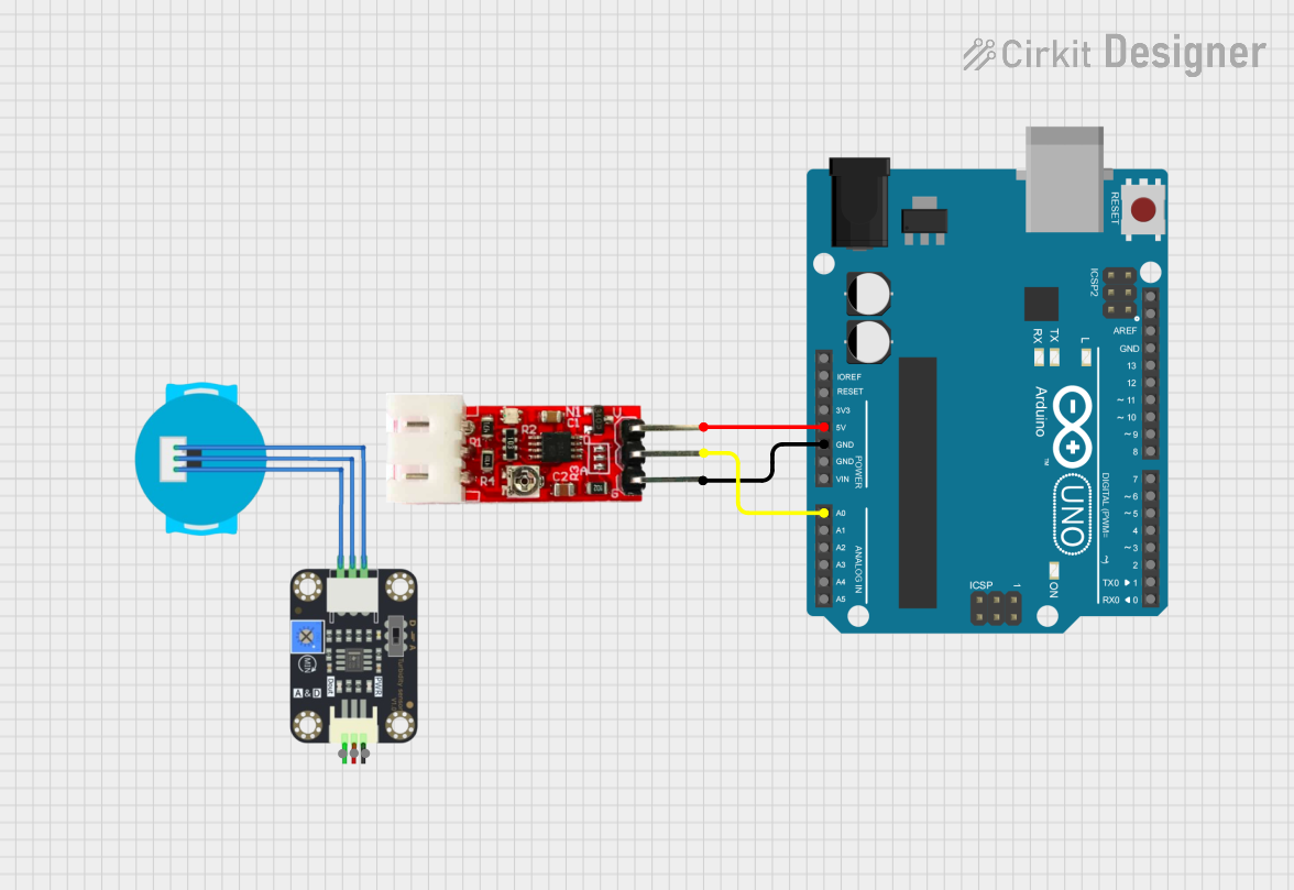
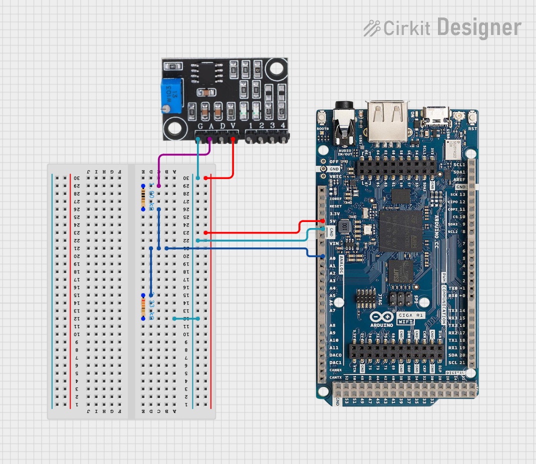
How to Use the Component in a Circuit

  1. Connect the VCC pin to a 5V power supply.
  2. Connect the GND pin to the ground of the power supply.
  3. Connect the AOUT pin to an analog input on a microcontroller, such as an Arduino UNO.
  4. Ensure that the sensor is properly submerged in the liquid to be tested without touching the bottom or sides of the container.

Important Considerations and Best Practices

  • Avoid exposing the sensor to direct sunlight or high-intensity light sources, as this can affect the readings.
  • Regularly clean the sensor to prevent buildup of debris, which can impact accuracy.
  • Calibrate the sensor periodically using standard turbidity solutions to maintain measurement accuracy.
  • Implement a stable power supply to prevent fluctuations that could cause erroneous readings.

Example Code for Arduino UNO

// Define the analog pin connected to the sensor's output
const int turbidityPin = A0;

void setup() {
  // Initialize serial communication at 9600 baud rate
  Serial.begin(9600);
}

void loop() {
  // Read the analog value from the turbidity sensor
  int sensorValue = analogRead(turbidityPin);
  // Convert the analog value to voltage
  float voltage = sensorValue * (5.0 / 1023.0);
  // Print the voltage to the Serial Monitor
  Serial.print("Turbidity Voltage: ");
  Serial.println(voltage);
  // Delay for a stable reading
  delay(1000);
}

Troubleshooting and FAQs

Common Issues Users Might Face

  • Inaccurate Readings: Ensure the sensor is clean and calibrated. Check for any electrical noise or interference in the circuit.
  • No Readings: Verify that the sensor is correctly powered and that all connections are secure. Check the analog pin for proper communication with the microcontroller.
  • Fluctuating Readings: Stabilize the liquid being measured to avoid rapid changes in turbidity. Ensure a consistent power supply.

Solutions and Tips for Troubleshooting

  • If the sensor is not responding, check the power supply and wiring connections.
  • For fluctuating readings, implement a moving average in the code to smooth out the data.
  • If the sensor is still not functioning correctly, replace it as it may be damaged.

FAQs

Q: Can the turbidity module be used in saltwater? A: Yes, but ensure that the sensor is rated for use in saline environments to prevent corrosion.

Q: How often should the sensor be calibrated? A: Calibration frequency depends on usage, but it is generally recommended to calibrate the sensor every few months or after any maintenance.

Q: What is the best way to clean the sensor? A: Use distilled water and a soft brush to gently clean the sensor. Avoid using harsh chemicals that could damage the sensor's optical components.