How to Use ATmega2560+Node MCU ESP8266 CH340G Compatible Board: Examples, Pinouts, and Specs
Introduction
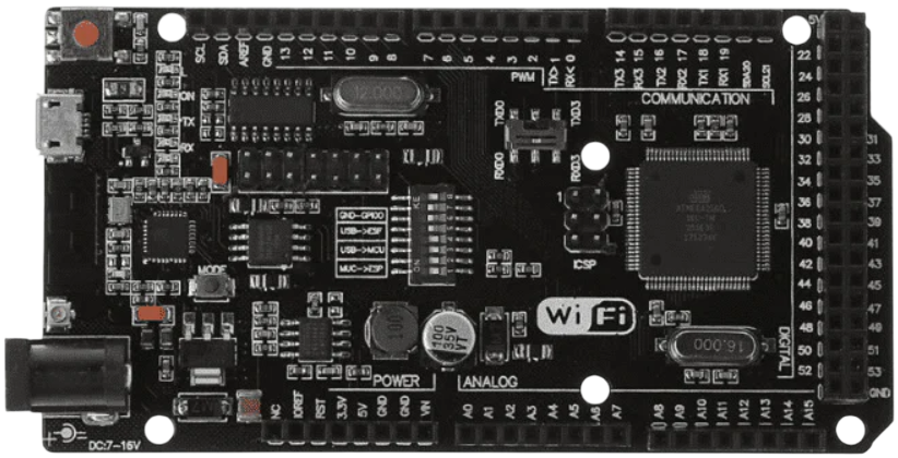
The ATmega2560+Node MCU ESP8266 CH340G Compatible Board is a powerful and versatile microcontroller board that integrates the ATmega2560 microcontroller with the Node MCU ESP8266 Wi-Fi module. This combination allows users to create complex projects that require both high processing power and wireless connectivity. The CH340G chip ensures seamless USB-to-serial communication, making programming and debugging straightforward.
Explore Projects Built with ATmega2560+Node MCU ESP8266 CH340G Compatible Board

Explore Projects Built with ATmega2560+Node MCU ESP8266 CH340G Compatible Board
Common Applications and Use Cases
- IoT (Internet of Things) projects requiring Wi-Fi connectivity
- Home automation systems
- Robotics and automation
- Data logging and remote monitoring
- Wireless sensor networks
- Educational projects for learning microcontroller programming and wireless communication
Technical Specifications
Key Technical Details
| Parameter | Specification |
|---|---|
| Microcontroller | ATmega2560 |
| Wi-Fi Module | Node MCU ESP8266 |
| USB-to-Serial Chip | CH340G |
| Operating Voltage | 5V (ATmega2560) / 3.3V (ESP8266) |
| Input Voltage (recommended) | 7-12V |
| Input Voltage (limits) | 6-20V |
| Digital I/O Pins | 54 (15 PWM outputs) |
| Analog Input Pins | 16 |
| Flash Memory | 256 KB (8 KB used by bootloader) |
| SRAM | 8 KB |
| EEPROM | 4 KB |
| Clock Speed | 16 MHz |
| Wi-Fi Standards | 802.11 b/g/n |
| USB Connector | Micro USB |
Pin Configuration and Descriptions
ATmega2560 Pinout
| Pin Name | Description |
|---|---|
| Digital Pins | 0-53: General-purpose digital I/O pins |
| PWM Pins | 2-13, 44-46: Pulse Width Modulation outputs |
| Analog Pins | A0-A15: Analog inputs (10-bit resolution) |
| Power Pins | VIN, 5V, 3.3V, GND: Power supply and ground |
| Communication | TX/RX: UART, SDA/SCL: I2C, SCK/MISO/MOSI: SPI |
| Reset | Resets the microcontroller |
Node MCU ESP8266 Pinout
| Pin Name | Description |
|---|---|
| TX/RX | UART communication pins |
| GPIO Pins | General-purpose I/O pins |
| EN | Enable pin for the ESP8266 module |
| RST | Reset pin for the ESP8266 module |
| CH_PD | Chip power-down pin |
Usage Instructions
How to Use the Component in a Circuit
Powering the Board:
- Use a 7-12V DC power supply via the barrel jack or VIN pin.
- Alternatively, connect the board to a computer using a Micro USB cable for both power and programming.
Programming the ATmega2560:
- Install the CH340G driver on your computer to enable USB-to-serial communication.
- Use the Arduino IDE to write and upload code to the ATmega2560. Select "Arduino Mega 2560" as the board in the IDE.
Using the ESP8266 Wi-Fi Module:
- The ESP8266 can be programmed separately or controlled via the ATmega2560 using AT commands.
- Ensure proper voltage levels (3.3V) for the ESP8266 to avoid damage.
Connecting Peripherals:
- Use the digital and analog pins to connect sensors, actuators, and other peripherals.
- For communication with external devices, use UART, I2C, or SPI interfaces.
Important Considerations and Best Practices
- Voltage Levels: The ESP8266 operates at 3.3V. Use a level shifter or voltage divider when interfacing with 5V logic.
- Power Supply: Ensure the power supply can provide sufficient current for both the ATmega2560 and ESP8266.
- Wi-Fi Configuration: Configure the ESP8266 for your Wi-Fi network using AT commands or custom firmware.
- Debugging: Use the serial monitor in the Arduino IDE to debug your code and monitor communication.
Example Code for Arduino UNO
Below is an example of how to use the ATmega2560 to communicate with the ESP8266 module and send data to a server:
#include <SoftwareSerial.h>

// Define RX and TX pins for ESP8266 communication
SoftwareSerial espSerial(10, 11); // RX, TX

void setup() {
  Serial.begin(9600); // Initialize Serial Monitor
  espSerial.begin(115200); // Initialize ESP8266 communication

  // Send AT command to test communication
  espSerial.println("AT");
  delay(1000);

  // Check for response from ESP8266
  if (espSerial.available()) {
    while (espSerial.available()) {
      Serial.write(espSerial.read()); // Print ESP8266 response to Serial Monitor
    }
  } else {
    Serial.println("No response from ESP8266");
  }
}

void loop() {
  // Example: Send data to a server (replace with your server details)
  espSerial.println("AT+CIPSTART=\"TCP\",\"example.com\",80"); // Connect to server
  delay(2000);

  espSerial.println("AT+CIPSEND=18"); // Send 18 bytes of data
  delay(1000);

  espSerial.println("GET / HTTP/1.1"); // HTTP GET request
  espSerial.println("Host: example.com");
  espSerial.println();
  delay(2000);

  // Print server response
  while (espSerial.available()) {
    Serial.write(espSerial.read());
  }
}
Troubleshooting and FAQs
Common Issues and Solutions
No Response from ESP8266:
- Ensure the ESP8266 is powered correctly (3.3V).
- Check the RX/TX connections between the ATmega2560 and ESP8266.
- Verify the baud rate of the ESP8266 (default is 115200).
CH340G Driver Not Recognized:
- Install the correct CH340G driver for your operating system.
- Use a different USB cable or port if the issue persists.
Wi-Fi Connection Fails:
- Double-check the SSID and password in your code.
- Ensure the Wi-Fi network is within range and supports 2.4 GHz (ESP8266 does not support 5 GHz).
Board Not Detected in Arduino IDE:
- Select the correct COM port and board type ("Arduino Mega 2560").
- Restart the Arduino IDE and reconnect the board.
FAQs
Q: Can I program the ESP8266 directly?
A: Yes, you can program the ESP8266 using the Arduino IDE or other tools. Ensure the ATmega2560 is not interfering with the ESP8266 during programming.
Q: How do I reset the ESP8266?
A: Use the RST pin on the ESP8266 module or send the "AT+RST" command via serial communication.
Q: Can I use the board for battery-powered projects?
A: Yes, but ensure the battery provides sufficient voltage and current for both the ATmega2560 and ESP8266. Use a voltage regulator if necessary.