Cirkit Designer Logo
Cirkit Designer
Your all-in-one circuit design IDE
Home / 
Component Documentation

How to Use MCP3208 AD-Wandler: Examples, Pinouts, and Specs

Image of MCP3208 AD-Wandler
Cirkit Designer LogoDesign with MCP3208 AD-Wandler in Cirkit Designer

Introduction

The MCP3208 is a 12-bit analog-to-digital converter (ADC) with 8 input channels, designed to convert analog signals into precise digital data. It operates using the Serial Peripheral Interface (SPI) protocol, ensuring efficient communication with microcontrollers and other digital systems. The MCP3208 is widely used in embedded systems, data acquisition, and sensor interfacing applications due to its high resolution, low power consumption, and versatile input configuration.

Explore Projects Built with MCP3208 AD-Wandler

Use Cirkit Designer to design, explore, and prototype these projects online. Some projects support real-time simulation. Click "Open Project" to start designing instantly!
I2C-Controlled Relay Switching with ESP32 and MCP23017 for Home Automation
Image of Vloerverwarming: A project utilizing MCP3208 AD-Wandler in a practical application
This circuit appears to be a control system utilizing two MCP23017 I/O expanders interfaced with an Olimex ESP32-EVB microcontroller via I2C communication, as indicated by the SDA and SCL connections with pull-up resistors. The MCP23017 expanders control an 8-channel relay module, allowing the microcontroller to switch various loads, potentially for home automation or industrial control. Additionally, there is an Adafruit ADS1115 16-bit ADC for analog signal measurement, and several heating actuators and a thermostat are connected, suggesting temperature control functionality.
Cirkit Designer LogoOpen Project in Cirkit Designer
MCP23017-Expanded I/O Interface with ADS1115 ADC and ESP32 Control
Image of door and window sensors: A project utilizing MCP3208 AD-Wandler in a practical application
This circuit features two MCP23017 I/O expanders interfaced with multiple switches, allowing for the expansion of input capabilities. The MCP23017s are connected via I2C to an Olimex ESP32-EVB microcontroller, which likely manages the input states from the switches. Additionally, an Adafruit ADS1115 16-bit ADC is included, suggesting that some analog inputs are being monitored, with the ADC also interfaced with the ESP32 via I2C.
Cirkit Designer LogoOpen Project in Cirkit Designer
ESP32-Based I2C Communication Hub with Multiplexer and Expander
Image of Lights: A project utilizing MCP3208 AD-Wandler in a practical application
This circuit features an Olimex ESP32-EVB microcontroller unit (MCU) for processing and connectivity, interfaced with an MCP23017 I/O expander and an Adafruit TCA9548A I2C multiplexer to expand the number of I/O lines and allow multiple I2C devices to communicate with the MCU over the same bus. Pull-up resistors are connected to the I2C lines for proper bus operation, and both the MCP23017 and TCA9548A have their reset lines pulled high, likely for normal operation without external reset control.
Cirkit Designer LogoOpen Project in Cirkit Designer
ESP32-C3 Mini and MCP4725 DAC Controlled Analog Output Circuit
Image of pp: A project utilizing MCP3208 AD-Wandler in a practical application
This circuit features an ESP32-C3 Mini microcontroller that interfaces with an Adafruit MCP4725 DAC via I2C for analog output, which is then fed into an OPA2333 operational amplifier. Power management is handled by a 5V step-down voltage regulator that receives power from a 2000mAh battery and supplies the ESP32-C3 and a 3.3V AMS1117 voltage regulator. Additionally, the circuit includes user input through buttons and electro pads, with debouncing provided by resistors.
Cirkit Designer LogoOpen Project in Cirkit Designer

Explore Projects Built with MCP3208 AD-Wandler

Use Cirkit Designer to design, explore, and prototype these projects online. Some projects support real-time simulation. Click "Open Project" to start designing instantly!
Image of Vloerverwarming: A project utilizing MCP3208 AD-Wandler in a practical application
I2C-Controlled Relay Switching with ESP32 and MCP23017 for Home Automation
This circuit appears to be a control system utilizing two MCP23017 I/O expanders interfaced with an Olimex ESP32-EVB microcontroller via I2C communication, as indicated by the SDA and SCL connections with pull-up resistors. The MCP23017 expanders control an 8-channel relay module, allowing the microcontroller to switch various loads, potentially for home automation or industrial control. Additionally, there is an Adafruit ADS1115 16-bit ADC for analog signal measurement, and several heating actuators and a thermostat are connected, suggesting temperature control functionality.
Cirkit Designer LogoOpen Project in Cirkit Designer
Image of door and window sensors: A project utilizing MCP3208 AD-Wandler in a practical application
MCP23017-Expanded I/O Interface with ADS1115 ADC and ESP32 Control
This circuit features two MCP23017 I/O expanders interfaced with multiple switches, allowing for the expansion of input capabilities. The MCP23017s are connected via I2C to an Olimex ESP32-EVB microcontroller, which likely manages the input states from the switches. Additionally, an Adafruit ADS1115 16-bit ADC is included, suggesting that some analog inputs are being monitored, with the ADC also interfaced with the ESP32 via I2C.
Cirkit Designer LogoOpen Project in Cirkit Designer
Image of Lights: A project utilizing MCP3208 AD-Wandler in a practical application
ESP32-Based I2C Communication Hub with Multiplexer and Expander
This circuit features an Olimex ESP32-EVB microcontroller unit (MCU) for processing and connectivity, interfaced with an MCP23017 I/O expander and an Adafruit TCA9548A I2C multiplexer to expand the number of I/O lines and allow multiple I2C devices to communicate with the MCU over the same bus. Pull-up resistors are connected to the I2C lines for proper bus operation, and both the MCP23017 and TCA9548A have their reset lines pulled high, likely for normal operation without external reset control.
Cirkit Designer LogoOpen Project in Cirkit Designer
Image of pp: A project utilizing MCP3208 AD-Wandler in a practical application
ESP32-C3 Mini and MCP4725 DAC Controlled Analog Output Circuit
This circuit features an ESP32-C3 Mini microcontroller that interfaces with an Adafruit MCP4725 DAC via I2C for analog output, which is then fed into an OPA2333 operational amplifier. Power management is handled by a 5V step-down voltage regulator that receives power from a 2000mAh battery and supplies the ESP32-C3 and a 3.3V AMS1117 voltage regulator. Additionally, the circuit includes user input through buttons and electro pads, with debouncing provided by resistors.
Cirkit Designer LogoOpen Project in Cirkit Designer

Common Applications and Use Cases

  • Sensor data acquisition (e.g., temperature, pressure, light sensors)
  • Industrial automation and control systems
  • Portable data logging devices
  • Audio signal processing
  • Robotics and IoT applications

Technical Specifications

The MCP3208 offers robust performance and flexibility, making it suitable for a wide range of applications. Below are its key technical specifications:

Parameter Value
Resolution 12-bit
Number of Input Channels 8
Input Voltage Range 0V to VREF
Reference Voltage (VREF) 2.7V to 5.5V
Supply Voltage (VDD) 2.7V to 5.5V
Maximum Sampling Rate 100 ksps (at 5V)
Communication Interface SPI (Serial Peripheral Interface)
Power Consumption 500 µA (typical, active mode)
Package Options PDIP, SOIC, TSSOP
Operating Temperature Range -40°C to +85°C

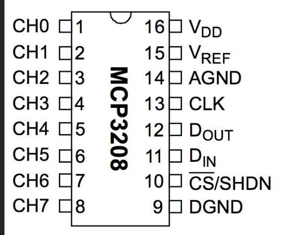
Pin Configuration and Descriptions

The MCP3208 has 16 pins, with the following configuration:

Pin Number Pin Name Description
1 CH0 Analog input channel 0
2 CH1 Analog input channel 1
3 CH2 Analog input channel 2
4 CH3 Analog input channel 3
5 CH4 Analog input channel 4
6 CH5 Analog input channel 5
7 CH6 Analog input channel 6
8 CH7 Analog input channel 7
9 DGND Digital ground
10 CS/SHDN Chip Select / Shutdown control
11 DIN Data input (SPI MOSI)
12 DOUT Data output (SPI MISO)
13 CLK Serial clock input (SPI SCK)
14 AGND Analog ground
15 VREF Reference voltage input
16 VDD Positive supply voltage

Usage Instructions

The MCP3208 is straightforward to use in a circuit, especially when interfaced with microcontrollers like the Arduino UNO. Below are the steps and considerations for using the MCP3208:

Connecting the MCP3208

  1. Power Supply: Connect the VDD pin to a 3.3V or 5V power source, and connect the AGND and DGND pins to ground.
  2. Reference Voltage: Provide a stable reference voltage to the VREF pin. This voltage determines the ADC's input range (0V to VREF).
  3. SPI Communication:
    • Connect the CS/SHDN pin to a digital output pin on the microcontroller (used to enable/disable the MCP3208).
    • Connect the DIN pin to the SPI MOSI pin on the microcontroller.
    • Connect the DOUT pin to the SPI MISO pin on the microcontroller.
    • Connect the CLK pin to the SPI SCK pin on the microcontroller.
  4. Analog Inputs: Connect up to 8 analog signals to the CH0–CH7 pins.

Example Code for Arduino UNO

Below is an example of how to interface the MCP3208 with an Arduino UNO to read an analog signal:

#include <SPI.h>

// Define MCP3208 pins
const int CS_PIN = 10; // Chip Select pin connected to Arduino pin 10

void setup() {
  pinMode(CS_PIN, OUTPUT); // Set CS pin as output
  digitalWrite(CS_PIN, HIGH); // Set CS pin high (inactive)
  SPI.begin(); // Initialize SPI communication
  Serial.begin(9600); // Initialize serial communication for debugging
}

int readMCP3208(int channel) {
  // Ensure the channel is valid (0-7)
  if (channel < 0 || channel > 7) return -1;

  // Start SPI communication
  digitalWrite(CS_PIN, LOW); // Activate the MCP3208

  // Send start bit, single-ended mode, and channel selection
  byte command = 0b00000110 | (channel >> 2);
  SPI.transfer(command); // Send the first byte
  byte highByte = SPI.transfer((channel & 0b11) << 6); // Send the second byte
  byte lowByte = SPI.transfer(0x00); // Send dummy byte to receive data

  digitalWrite(CS_PIN, HIGH); // Deactivate the MCP3208

  // Combine the received bytes into a 12-bit result
  int result = ((highByte & 0b00001111) << 8) | lowByte;
  return result;
}

void loop() {
  int adcValue = readMCP3208(0); // Read from channel 0
  Serial.print("ADC Value: ");
  Serial.println(adcValue); // Print the ADC value
  delay(500); // Wait for 500ms
}

Important Considerations

  • Reference Voltage: Ensure the reference voltage is stable and noise-free for accurate ADC readings.
  • Input Impedance: The MCP3208 has a finite input impedance. Use a buffer circuit if the signal source has high impedance.
  • SPI Speed: The SPI clock frequency should not exceed 2 MHz for proper operation.
  • Decoupling Capacitors: Place a 0.1 µF capacitor close to the VDD and VREF pins to reduce noise.

Troubleshooting and FAQs

Common Issues

  1. Incorrect ADC Readings:

    • Ensure the reference voltage is stable and within the specified range.
    • Verify the SPI connections and ensure the correct SPI mode (Mode 0) is used.
  2. No Output from MCP3208:

    • Check the CS/SHDN pin. It must be pulled low during communication.
    • Verify the power supply and ground connections.
  3. Noise in ADC Output:

    • Use proper shielding and grounding techniques.
    • Add decoupling capacitors near the power supply and reference voltage pins.

FAQs

Q: Can the MCP3208 handle negative input voltages?
A: No, the MCP3208 can only measure voltages in the range of 0V to VREF. Negative voltages may damage the device.

Q: What is the maximum sampling rate of the MCP3208?
A: The maximum sampling rate is 100 ksps when operating at 5V.

Q: Can I use fewer than 8 channels?
A: Yes, you can use as many channels as needed. Unused channels can be left unconnected.

Q: Is the MCP3208 compatible with 3.3V systems?
A: Yes, the MCP3208 operates with supply voltages as low as 2.7V, making it compatible with 3.3V systems.