How to Use NXP BMS: Examples, Pinouts, and Specs
Introduction
The NXP Battery Management System (BMS) is a highly advanced solution designed to monitor and manage the performance of battery packs. It ensures safety, efficiency, and longevity by providing precise control and monitoring of battery parameters. This system is ideal for applications such as electric vehicles (EVs), renewable energy storage systems, industrial equipment, and portable electronics.
By integrating the NXP BMS into your design, you can achieve enhanced battery safety, optimized charging and discharging cycles, and extended battery life. Its robust design and advanced features make it a reliable choice for modern energy management systems.
Explore Projects Built with NXP BMS


Explore Projects Built with NXP BMS
Technical Specifications
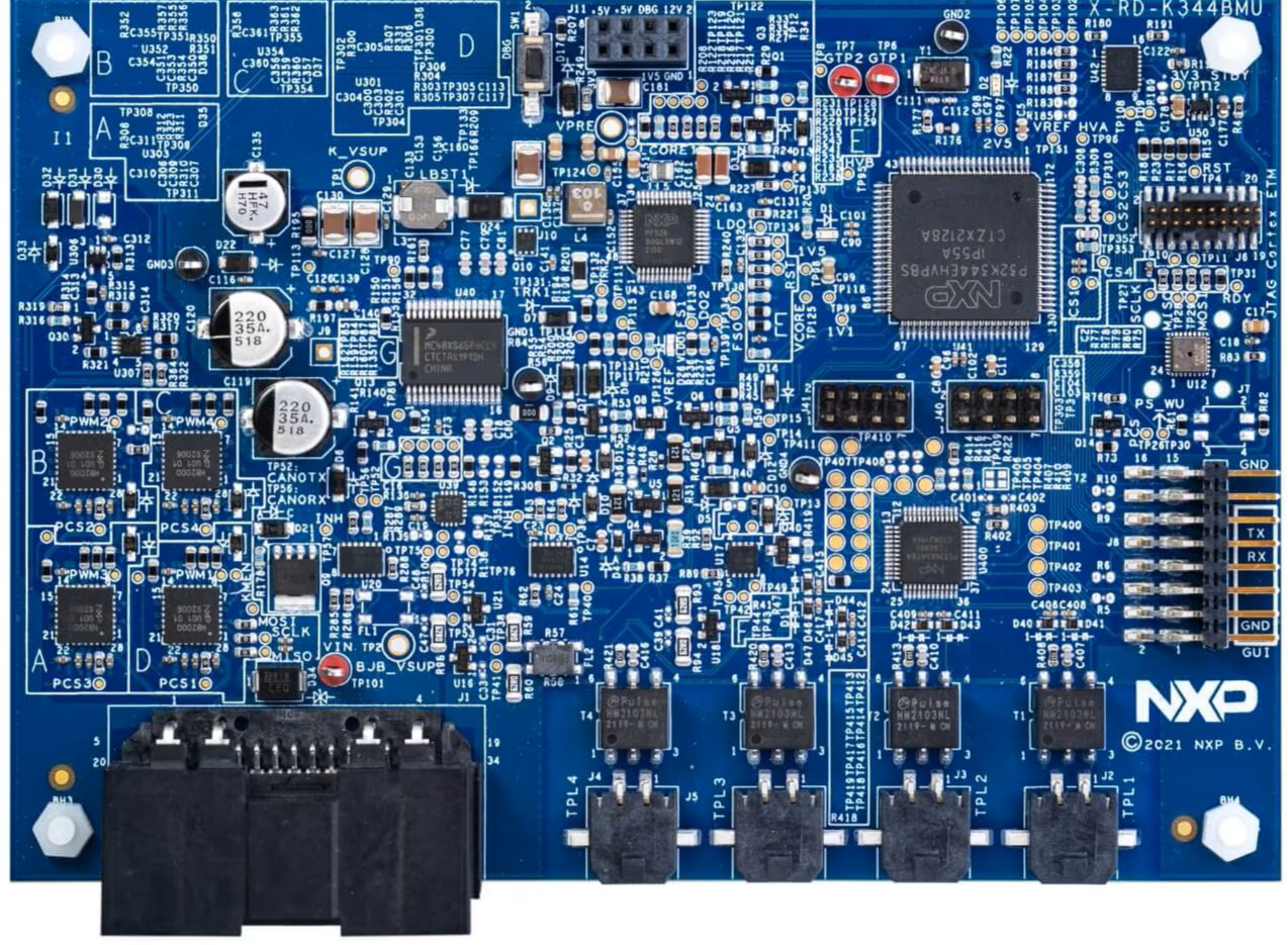
The NXP BMS (Part ID: 1) is equipped with a range of features to support efficient battery management. Below are the key technical specifications:
General Specifications
| Parameter | Value |
|---|---|
| Manufacturer | NXP |
| Part ID | 1 |
| Operating Voltage Range | 3.3V to 5V |
| Maximum Current Monitoring | Up to 200A |
| Temperature Range | -40°C to 125°C |
| Communication Interface | SPI, I2C, CAN |
| Cell Voltage Monitoring | 1V to 5V per cell |
| Supported Battery Types | Lithium-ion, Lithium-polymer, etc. |
Pin Configuration and Descriptions
The NXP BMS typically comes in a multi-pin package. Below is the pin configuration:
| Pin Number | Pin Name | Description |
|---|---|---|
| 1 | VCC | Power supply input (3.3V to 5V) |
| 2 | GND | Ground connection |
| 3 | SPI_MOSI | SPI Master Out Slave In (data input) |
| 4 | SPI_MISO | SPI Master In Slave Out (data output) |
| 5 | SPI_CLK | SPI Clock |
| 6 | I2C_SCL | I2C Clock |
| 7 | I2C_SDA | I2C Data |
| 8 | CAN_H | CAN Bus High |
| 9 | CAN_L | CAN Bus Low |
| 10 | TEMP_SENSOR | Temperature sensor input |
| 11 | CELL_VOLTAGE | Battery cell voltage monitoring input |
| 12 | ALERT | Fault or alert signal output |
Usage Instructions
To use the NXP BMS in a circuit, follow these steps:
- Power Supply: Connect the VCC pin to a stable 3.3V or 5V power source and the GND pin to the ground.
- Communication Interface: Choose the appropriate communication protocol (SPI, I2C, or CAN) based on your application. Connect the corresponding pins (e.g., SPI_MOSI, SPI_MISO, SPI_CLK for SPI) to your microcontroller or processor.
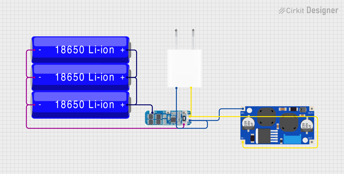
- Battery Connections: Connect the battery cells to the CELL_VOLTAGE pin(s) for monitoring. Ensure proper scaling and protection circuits are in place.
- Temperature Monitoring: Attach a compatible temperature sensor to the TEMP_SENSOR pin to monitor battery temperature.
- Fault Handling: Use the ALERT pin to detect and respond to fault conditions such as overvoltage, undervoltage, or overtemperature.
Important Considerations
- Voltage Levels: Ensure that the operating voltage of the BMS matches the voltage levels of your system.
- Communication Protocols: Configure the communication interface (SPI, I2C, or CAN) correctly in your microcontroller's firmware.
- Battery Safety: Always include appropriate protection circuits (e.g., fuses, diodes) to prevent damage to the BMS or battery pack.
- Thermal Management: Ensure proper heat dissipation to maintain the BMS within its operating temperature range.
Example Code for Arduino UNO (Using I2C)
Below is an example of how to interface the NXP BMS with an Arduino UNO using the I2C protocol:
#include <Wire.h> // Include the Wire library for I2C communication

#define BMS_I2C_ADDRESS 0x48 // Replace with the actual I2C address of the BMS

void setup() {
  Wire.begin(); // Initialize I2C communication
  Serial.begin(9600); // Start serial communication for debugging

  // Send initialization command to the BMS
  Wire.beginTransmission(BMS_I2C_ADDRESS);
  Wire.write(0x01); // Example command to initialize the BMS
  Wire.endTransmission();

  Serial.println("BMS Initialized");
}

void loop() {
  // Request battery voltage data from the BMS
  Wire.beginTransmission(BMS_I2C_ADDRESS);
  Wire.write(0x02); // Example command to request voltage data
  Wire.endTransmission();

  Wire.requestFrom(BMS_I2C_ADDRESS, 2); // Request 2 bytes of data
  if (Wire.available() == 2) {
    int voltage = Wire.read() << 8 | Wire.read(); // Combine two bytes into an integer
    Serial.print("Battery Voltage: ");
    Serial.print(voltage);
    Serial.println(" mV");
  }

  delay(1000); // Wait for 1 second before the next reading
}
Troubleshooting and FAQs
Common Issues and Solutions
No Communication with the BMS
- Cause: Incorrect wiring or communication protocol configuration.
- Solution: Double-check the connections and ensure the correct protocol (SPI, I2C, or CAN) is selected and configured in your microcontroller.
Inaccurate Voltage Readings
- Cause: Improper scaling or noise in the voltage monitoring circuit.
- Solution: Verify the input scaling resistors and ensure proper grounding and shielding.
Overheating
- Cause: Excessive current draw or poor thermal management.
- Solution: Ensure adequate heat dissipation and verify that the current draw is within the specified limits.
Alert Pin Triggered
- Cause: Fault condition such as overvoltage, undervoltage, or overtemperature.
- Solution: Check the battery parameters and address the fault condition before resetting the BMS.
FAQs
Q: Can the NXP BMS handle multiple battery cells?
- A: Yes, the NXP BMS supports monitoring of multiple battery cells. Refer to the datasheet for the maximum number of cells supported.
Q: Is the BMS compatible with lithium-ion batteries?
- A: Yes, the NXP BMS is designed to work with lithium-ion, lithium-polymer, and other battery chemistries.
Q: What is the maximum current the BMS can monitor?
- A: The NXP BMS can monitor currents up to 200A, depending on the configuration.
Q: Can I use the BMS with an Arduino?
- A: Yes, the BMS can be interfaced with an Arduino using SPI, I2C, or CAN protocols.
By following this documentation, you can effectively integrate the NXP BMS into your project and ensure reliable battery management.