
How to Use LSM6DS3 (Internally BMI160): Examples, Pinouts, and Specs
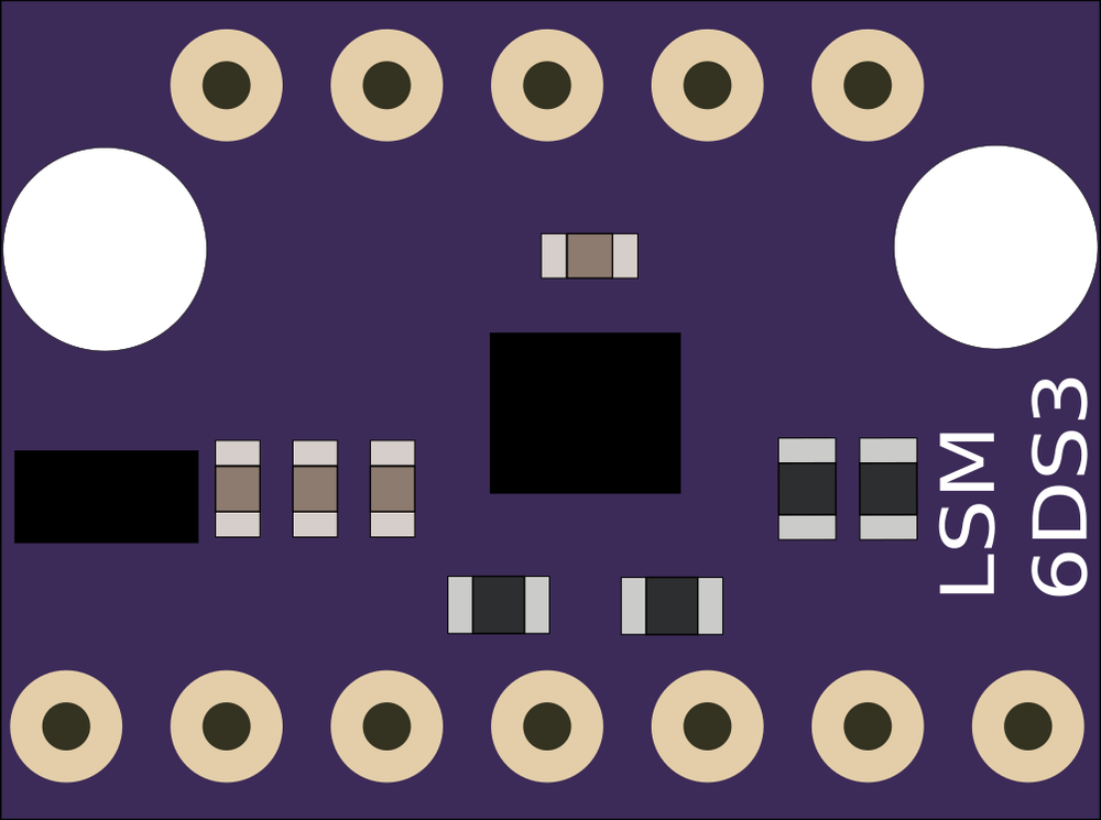
 Design with LSM6DS3 (Internally BMI160) in Cirkit Designer
Introduction
The LSM6DS3 is a 6-axis Inertial Measurement Unit (IMU) that integrates a 3-axis accelerometer and a 3-axis gyroscope into a single compact package. Manufactured by Alibaba, this sensor is designed for precise motion tracking and orientation detection. It is widely used in applications such as smartphones, wearables, gaming devices, robotics, and IoT systems. The LSM6DS3 is known for its low power consumption and high performance, making it ideal for battery-powered devices. Internally, it shares similarities with the BMI160 sensor, offering comparable functionality and reliability.
Explore Projects Built with LSM6DS3 (Internally BMI160)
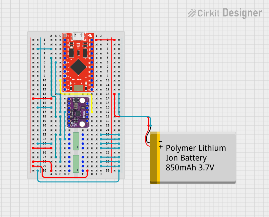 Open Project in Cirkit Designer
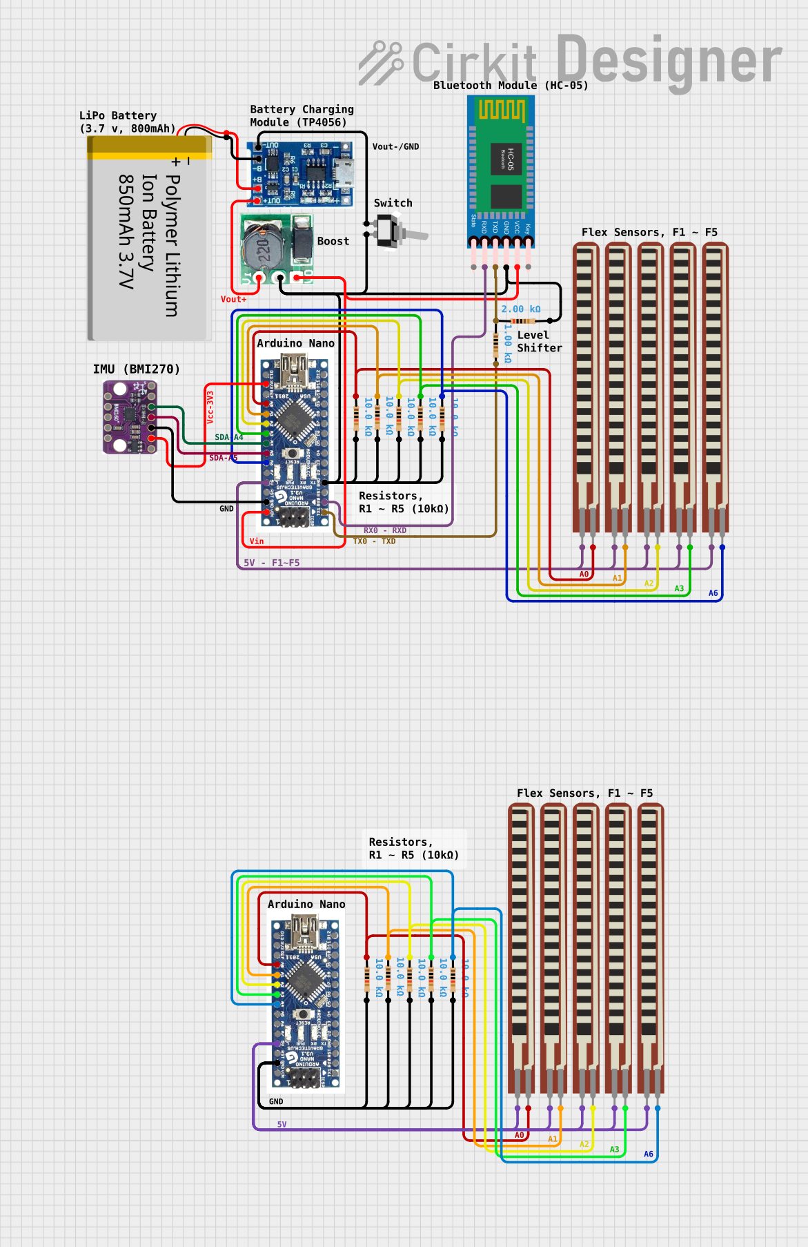 Open Project in Cirkit Designer
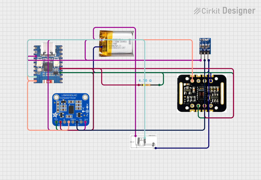 Open Project in Cirkit Designer
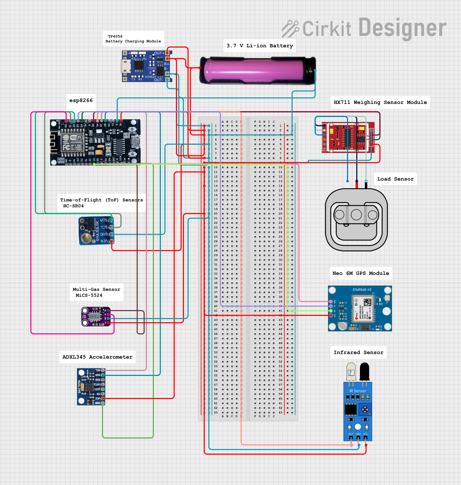 Open Project in Cirkit Designer
Explore Projects Built with LSM6DS3 (Internally BMI160)
Open Project in Cirkit DesignerOpen Project in Cirkit DesignerOpen Project in Cirkit DesignerOpen Project in Cirkit DesignerCommon Applications:
- Motion tracking in smartphones and tablets
- Fitness and health monitoring in wearables
- Gesture recognition in gaming controllers
- Stabilization in drones and robotics
- Orientation detection in IoT devices
Technical Specifications
Key Technical Details:
| Parameter | Value |
|---|---|
| Supply Voltage | 1.71V to 3.6V |
| Accelerometer Range | ±2g, ±4g, ±8g, ±16g |
| Gyroscope Range | ±125°/s, ±250°/s, ±500°/s, ±1000°/s, ±2000°/s |
| Output Data Rate (ODR) | Up to 6.66 kHz |
| Communication Interfaces | I²C (up to 1 MHz), SPI (up to 10 MHz) |
| Operating Temperature Range | -40°C to +85°C |
| Power Consumption | 0.9 mA (accelerometer + gyroscope in high-performance mode) |
Pin Configuration and Descriptions:
The LSM6DS3 comes in a 14-pin LGA package. Below is the pinout description:
| Pin Number | Pin Name | Description |
|---|---|---|
| 1 | VDD | Power supply (1.71V to 3.6V) |
| 2 | VDDIO | I/O interface voltage supply |
| 3 | GND | Ground |
| 4 | SCL/SPC | I²C clock line / SPI clock |
| 5 | SDA/SDI/SDO | I²C data line / SPI data input/output |
| 6 | CS | SPI chip select (active low) |
| 7 | INT1 | Interrupt 1 output |
| 8 | INT2 | Interrupt 2 output |
| 9-14 | NC | Not connected (leave floating) |
Usage Instructions
How to Use the LSM6DS3 in a Circuit:
- Power Supply: Connect the VDD pin to a 1.8V or 3.3V power source, and connect GND to the ground of your circuit.
- Communication Interface: Choose between I²C or SPI for communication:
- For I²C, connect the SCL and SDA pins to the corresponding lines on your microcontroller. Use pull-up resistors (typically 4.7kΩ) on both lines.
- For SPI, connect the SCL, SDA/SDI/SDO, and CS pins to the appropriate SPI lines on your microcontroller.
- Interrupts: Optionally, connect INT1 and/or INT2 to GPIO pins on your microcontroller to handle interrupts.
- Bypass Unused Pins: Leave NC pins floating as they are not connected internally.
Important Considerations:
- Use decoupling capacitors (e.g., 0.1 µF) close to the VDD and VDDIO pins to reduce noise.
- Ensure the I²C or SPI lines are properly terminated to avoid communication errors.
- Configure the sensor's registers to set the desired accelerometer and gyroscope ranges, ODR, and other parameters.
Example Code for Arduino UNO (I²C Interface):
Below is an example of how to initialize and read data from the LSM6DS3 using an Arduino UNO:
#include <Wire.h> // Include the Wire library for I²C communication

#define LSM6DS3_ADDR 0x6A // Default I²C address of the LSM6DS3
#define WHO_AM_I_REG 0x0F // Register to check device identity
#define CTRL1_XL 0x10     // Accelerometer control register
#define CTRL2_G 0x11      // Gyroscope control register
#define OUTX_L_XL 0x28    // Accelerometer X-axis low byte register

void setup() {
  Wire.begin(); // Initialize I²C communication
  Serial.begin(9600); // Start serial communication for debugging

  // Check if the sensor is connected
  Wire.beginTransmission(LSM6DS3_ADDR);
  Wire.write(WHO_AM_I_REG);
  Wire.endTransmission();
  Wire.requestFrom(LSM6DS3_ADDR, 1);
  if (Wire.available()) {
    byte whoAmI = Wire.read();
    if (whoAmI == 0x69) { // Expected WHO_AM_I response
      Serial.println("LSM6DS3 detected!");
    } else {
      Serial.println("Device not detected. Check connections.");
      while (1); // Halt execution
    }
  }

  // Configure accelerometer (±2g, 104 Hz ODR)
  Wire.beginTransmission(LSM6DS3_ADDR);
  Wire.write(CTRL1_XL);
  Wire.write(0x40); // 104 Hz ODR, ±2g range
  Wire.endTransmission();

  // Configure gyroscope (±250°/s, 104 Hz ODR)
  Wire.beginTransmission(LSM6DS3_ADDR);
  Wire.write(CTRL2_G);
  Wire.write(0x40); // 104 Hz ODR, ±250°/s range
  Wire.endTransmission();
}

void loop() {
  // Read accelerometer X-axis data
  Wire.beginTransmission(LSM6DS3_ADDR);
  Wire.write(OUTX_L_XL);
  Wire.endTransmission();
  Wire.requestFrom(LSM6DS3_ADDR, 2); // Request 2 bytes (low and high)
  if (Wire.available() == 2) {
    int16_t accelX = Wire.read() | (Wire.read() << 8); // Combine low and high bytes
    Serial.print("Accelerometer X: ");
    Serial.println(accelX);
  }
  delay(500); // Wait before the next reading
}
Troubleshooting and FAQs
Common Issues:
Device Not Detected:
- Ensure the correct I²C address (0x6A or 0x6B) is being used.
- Verify the wiring, especially the SCL and SDA connections.
- Check for proper pull-up resistors on the I²C lines.
No Data Output:
- Confirm that the sensor is powered correctly (VDD and GND connections).
- Ensure the accelerometer and gyroscope are enabled in the control registers.
Inconsistent Readings:
- Verify that the sensor is securely mounted to avoid vibrations.
- Use appropriate filtering techniques to reduce noise in the data.
Tips for Troubleshooting:
- Use an oscilloscope or logic analyzer to debug I²C or SPI communication.
- Check the power supply voltage to ensure it is within the specified range.
- Refer to the LSM6DS3 datasheet for detailed register descriptions and configuration options.
This concludes the documentation for the LSM6DS3 (Internally BMI160). For further assistance, consult the official datasheet or contact Alibaba support.