
How to Use LSM5DS3: Examples, Pinouts, and Specs
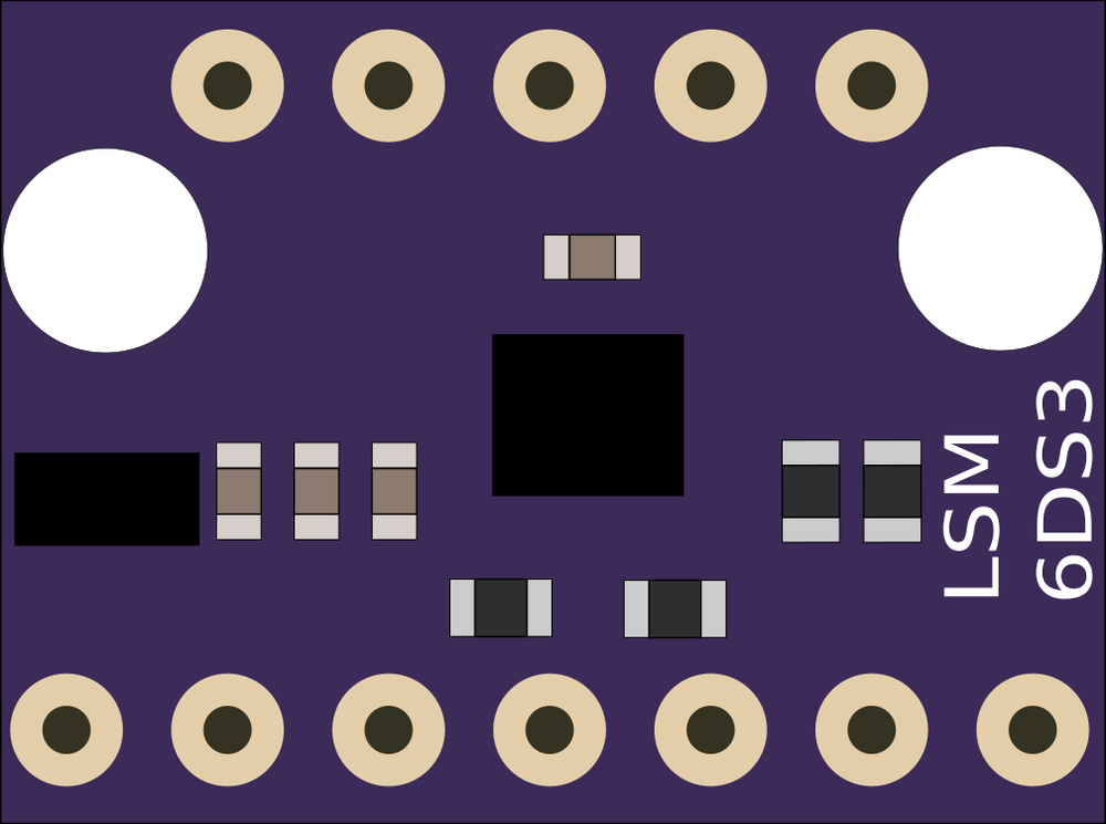
 Design with LSM5DS3 in Cirkit Designer
Introduction
The LSM5DS3 is a high-performance 6-axis inertial sensor manufactured by Alibaba. It integrates a 3-axis accelerometer and a 3-axis gyroscope into a single compact package, making it ideal for motion tracking and orientation detection. This sensor is widely used in applications such as smartphones, wearables, gaming devices, robotics, and industrial equipment. Its low power consumption and high precision make it suitable for battery-powered devices and real-time motion sensing.
Explore Projects Built with LSM5DS3
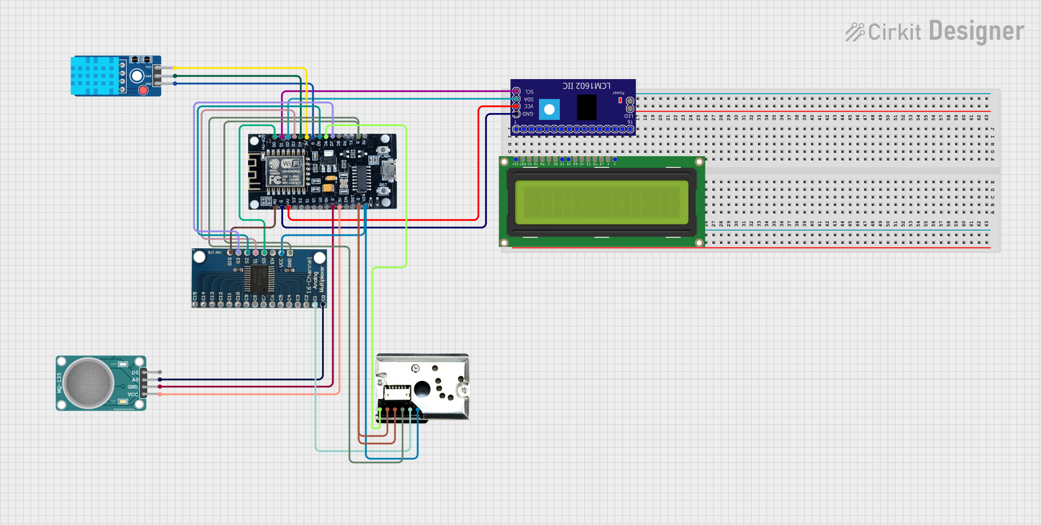 Open Project in Cirkit Designer
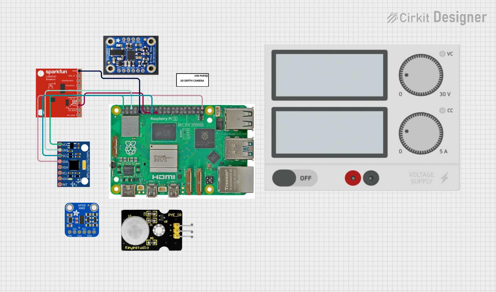 Open Project in Cirkit Designer
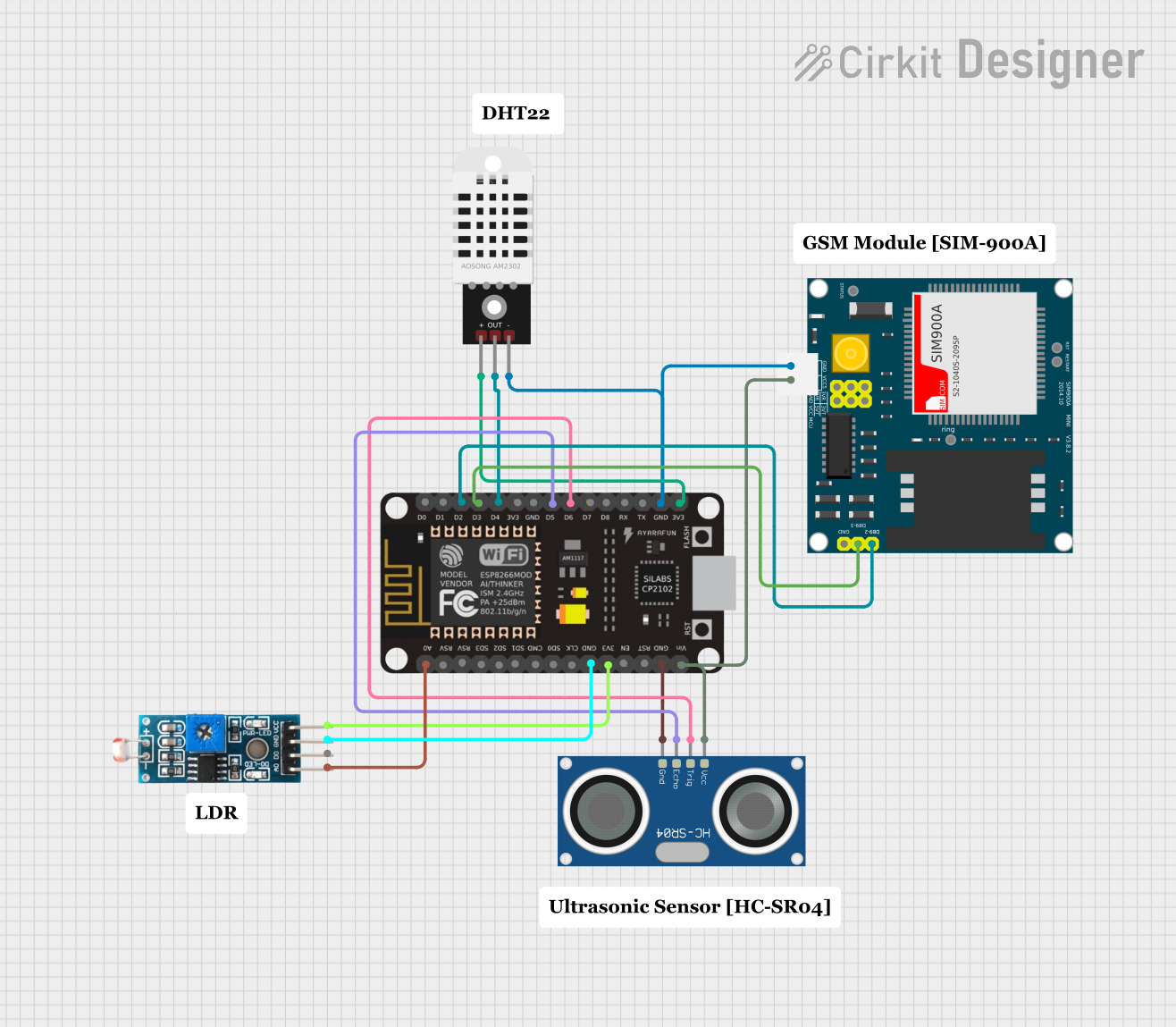 Open Project in Cirkit Designer
 Open Project in Cirkit Designer
Explore Projects Built with LSM5DS3
Open Project in Cirkit DesignerOpen Project in Cirkit DesignerOpen Project in Cirkit DesignerOpen Project in Cirkit DesignerCommon Applications:
- Motion tracking in smartphones and tablets
- Orientation detection in wearable devices
- Stabilization systems in drones and robotics
- Gesture recognition in gaming controllers
- Industrial equipment monitoring
Technical Specifications
Key Technical Details:
| Parameter | Value |
|---|---|
| Manufacturer | Alibaba |
| Part ID | LSM5DS3 |
| Sensor Type | 6-axis (3-axis accelerometer + 3-axis gyroscope) |
| Operating Voltage | 1.8V to 3.6V |
| Accelerometer Range | ±2g, ±4g, ±8g, ±16g |
| Gyroscope Range | ±125°/s, ±245°/s, ±500°/s, ±1000°/s, ±2000°/s |
| Output Data Rate (ODR) | Up to 6.66 kHz |
| Communication Interface | I²C (up to 400 kHz) / SPI (up to 10 MHz) |
| Operating Temperature Range | -40°C to +85°C |
| Package Type | LGA-14 (2.5 mm x 3.0 mm x 0.83 mm) |
| Power Consumption | 0.9 mA (accelerometer + gyroscope active) |
Pin Configuration and Descriptions:
The LSM5DS3 comes in a 14-pin LGA package. Below is the pinout and description:
| Pin Number | Pin Name | Description |
|---|---|---|
| 1 | VDD | Power supply (1.8V to 3.6V) |
| 2 | VDD_IO | I/O interface voltage supply |
| 3 | GND | Ground |
| 4 | SCL/SPC | I²C clock line / SPI clock |
| 5 | SDA/SDI/SDO | I²C data line / SPI data input/output |
| 6 | CS | SPI chip select (active low) |
| 7 | INT1 | Interrupt 1 output |
| 8 | INT2 | Interrupt 2 output |
| 9-14 | NC | Not connected (leave floating) |
Usage Instructions
How to Use the LSM5DS3 in a Circuit:
- Power Supply: Connect the VDD pin to a 1.8V to 3.6V power source and the GND pin to ground. Ensure the VDD_IO pin is connected to the same voltage level as the microcontroller's I/O voltage.
- Communication Interface: Choose between I²C or SPI for communication:
- For I²C, connect the SCL and SDA pins to the corresponding I²C lines on the microcontroller. Use pull-up resistors (typically 4.7 kΩ) on both lines.
- For SPI, connect the SPC, SDI/SDO, and CS pins to the SPI lines on the microcontroller.
- Interrupts: Use the INT1 and INT2 pins to configure interrupts for motion detection or other events.
- Bypass NC Pins: Leave the NC pins unconnected.
Important Considerations:
- Voltage Levels: Ensure the I/O voltage (VDD_IO) matches the microcontroller's logic level to avoid damage.
- Pull-Up Resistors: For I²C communication, always use pull-up resistors on the SCL and SDA lines.
- Mounting: The LSM5DS3 is sensitive to mechanical stress. Mount it carefully to avoid introducing noise or inaccuracies in measurements.
- Calibration: Perform sensor calibration to account for offsets and improve accuracy.
Example Code for Arduino UNO (I²C Interface):
#include <Wire.h>

#define LSM5DS3_ADDR 0x6A // I²C address of the LSM5DS3

// Register addresses
#define CTRL1_XL 0x10 // Accelerometer control register
#define CTRL2_G  0x11 // Gyroscope control register
#define OUTX_L_XL 0x28 // Accelerometer X-axis low byte
#define OUTX_L_G  0x22 // Gyroscope X-axis low byte

void setup() {
  Wire.begin(); // Initialize I²C communication
  Serial.begin(9600); // Initialize serial communication for debugging

  // Configure accelerometer (±2g, 104 Hz ODR)
  writeRegister(CTRL1_XL, 0x40);

  // Configure gyroscope (±245°/s, 104 Hz ODR)
  writeRegister(CTRL2_G, 0x40);

  Serial.println("LSM5DS3 initialized!");
}

void loop() {
  int16_t accelX = readAxis(OUTX_L_XL); // Read accelerometer X-axis
  int16_t gyroX = readAxis(OUTX_L_G);  // Read gyroscope X-axis

  // Print sensor data
  Serial.print("Accel X: ");
  Serial.print(accelX);
  Serial.print(" | Gyro X: ");
  Serial.println(gyroX);

  delay(500); // Delay for readability
}

// Function to write to a register
void writeRegister(uint8_t reg, uint8_t value) {
  Wire.beginTransmission(LSM5DS3_ADDR);
  Wire.write(reg);
  Wire.write(value);
  Wire.endTransmission();
}

// Function to read a 16-bit axis value
int16_t readAxis(uint8_t reg) {
  Wire.beginTransmission(LSM5DS3_ADDR);
  Wire.write(reg);
  Wire.endTransmission(false);
  Wire.requestFrom(LSM5DS3_ADDR, 2);

  uint8_t lsb = Wire.read();
  uint8_t msb = Wire.read();

  return (int16_t)(msb << 8 | lsb);
}
Troubleshooting and FAQs
Common Issues:
No Communication with the Sensor:
- Cause: Incorrect I²C address or wiring.
- Solution: Verify the I²C address (default is 0x6A) and check all connections.
Inaccurate Readings:
- Cause: Sensor not calibrated or mounted improperly.
- Solution: Perform calibration and ensure the sensor is securely mounted.
Interrupts Not Triggering:
- Cause: Incorrect interrupt configuration.
- Solution: Double-check the interrupt settings in the sensor's registers.
High Noise in Measurements:
- Cause: Electrical noise or mechanical vibrations.
- Solution: Add decoupling capacitors near the power pins and isolate the sensor from vibrations.
FAQs:
Q: Can the LSM5DS3 operate at 5V?
A: No, the maximum operating voltage is 3.6V. Use a voltage regulator or level shifter if needed.Q: How do I select between I²C and SPI?
A: The communication interface is selected based on how the CS pin is configured. Pull CS high for I²C and low for SPI.Q: What is the default accelerometer and gyroscope range?
A: The default range is ±2g for the accelerometer and ±245°/s for the gyroscope.Q: Can I use the LSM5DS3 for gesture recognition?
A: Yes, the sensor's high precision and interrupt capabilities make it suitable for gesture recognition applications.
This concludes the documentation for the LSM5DS3. For further details, refer to the manufacturer's datasheet or application notes.