How to Use ESP32-C3 Super Mini: Examples, Pinouts, and Specs
Introduction
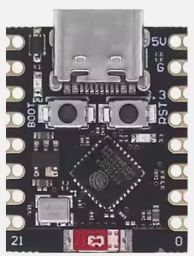
The ESP32-C3 Super Mini is a compact, low-power microcontroller designed for Internet of Things (IoT) applications. It features integrated Wi-Fi and Bluetooth Low Energy (BLE) capabilities, making it ideal for wireless communication in smart devices. Built on the RISC-V architecture, the ESP32-C3 Super Mini offers high performance, low power consumption, and robust security features, all in a small form factor.
Explore Projects Built with ESP32-C3 Super Mini


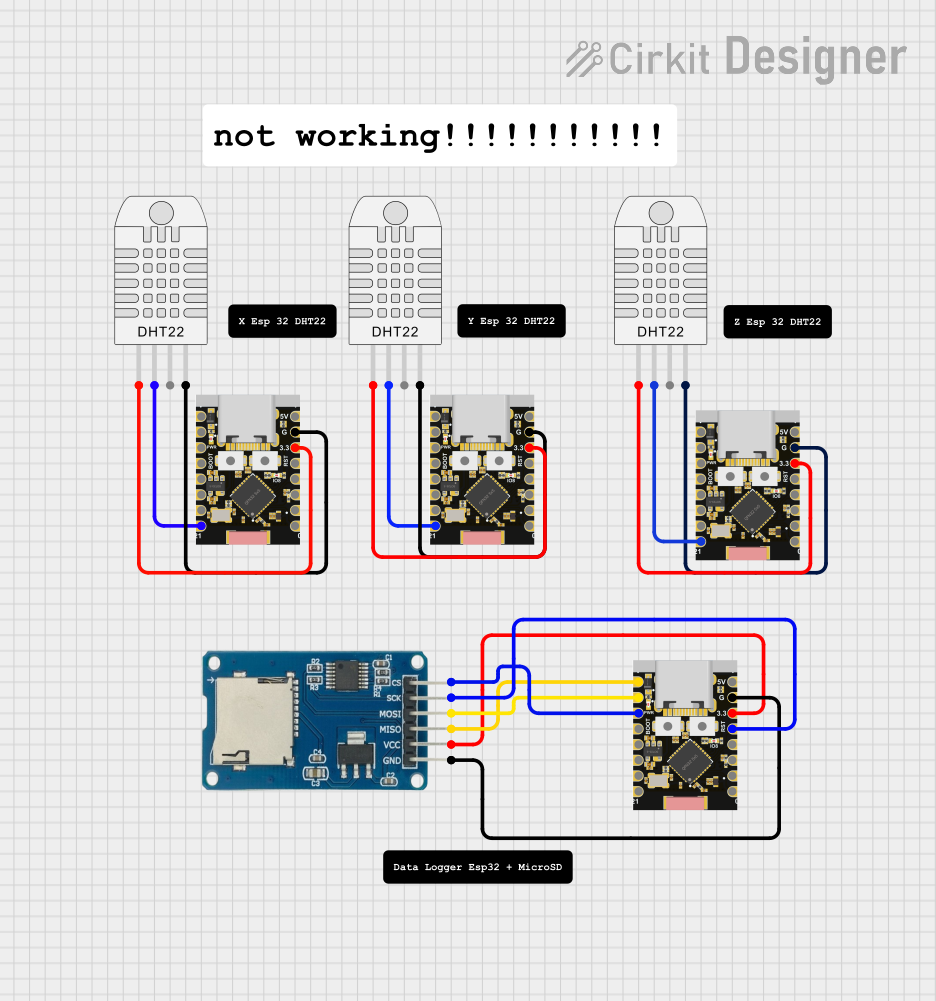
Explore Projects Built with ESP32-C3 Super Mini
Common Applications and Use Cases
- Smart home devices (e.g., smart plugs, lights, and sensors)
- Wearable technology
- Industrial IoT systems
- Wireless data logging and monitoring
- Remote control and automation systems
- Low-power Bluetooth beacons
Technical Specifications
The ESP32-C3 Super Mini is packed with features that make it versatile and efficient for a wide range of applications. Below are its key technical specifications:
| Specification | Details |
|---|---|
| Microcontroller Core | RISC-V 32-bit single-core processor, up to 160 MHz |
| Flash Memory | 4 MB (external SPI flash) |
| RAM | 400 KB SRAM |
| Wi-Fi | IEEE 802.11 b/g/n (2.4 GHz) |
| Bluetooth | Bluetooth 5.0 Low Energy (BLE) |
| GPIO Pins | 15 GPIO pins (multiplexed with other functions) |
| Operating Voltage | 3.3V |
| Power Consumption | Ultra-low power consumption in deep sleep mode (as low as 5 µA) |
| Security Features | Secure boot, flash encryption, and cryptographic hardware acceleration |
| Dimensions | 10 mm x 10 mm (approximate) |
Pin Configuration and Descriptions
The ESP32-C3 Super Mini has a compact pinout. Below is the pin configuration and description:
| Pin Name | Type | Description |
|---|---|---|
| VCC | Power | 3.3V power input |
| GND | Power | Ground |
| GPIO0 | GPIO/Boot | General-purpose I/O, also used for boot mode selection |
| GPIO1 | GPIO | General-purpose I/O |
| GPIO2 | GPIO | General-purpose I/O |
| GPIO3 | GPIO | General-purpose I/O |
| GPIO4 | GPIO | General-purpose I/O |
| GPIO5 | GPIO | General-purpose I/O |
| RXD | UART RX | UART receive pin |
| TXD | UART TX | UART transmit pin |
| EN | Enable | Chip enable pin (active high) |
| ADC1 | Analog Input | 12-bit ADC input |
| SPI_CLK | SPI Clock | SPI clock signal |
| SPI_MOSI | SPI Data Out | SPI master-out, slave-in |
| SPI_MISO | SPI Data In | SPI master-in, slave-out |
Usage Instructions
How to Use the ESP32-C3 Super Mini in a Circuit
- Powering the Module: Connect the VCC pin to a 3.3V power source and GND to ground.
- Programming the Module: Use a USB-to-UART adapter to connect the RXD and TXD pins to your computer. Ensure GPIO0 is pulled low during boot to enter programming mode.
- Connecting Peripherals: Use the GPIO pins to interface with sensors, actuators, or other devices. Configure the pins in your code as needed.
- Wi-Fi and Bluetooth Setup: Use the ESP-IDF (Espressif IoT Development Framework) or Arduino IDE to configure and program the Wi-Fi and Bluetooth functionalities.
Important Considerations and Best Practices
- Voltage Levels: Ensure all connected peripherals operate at 3.3V logic levels to avoid damaging the module.
- Antenna Placement: Avoid placing metal objects near the module's antenna to ensure optimal wireless performance.
- Deep Sleep Mode: Use deep sleep mode to minimize power consumption in battery-powered applications.
- Firmware Updates: Regularly update the firmware to benefit from the latest features and security patches.
Example Code for Arduino IDE
Below is an example of how to connect the ESP32-C3 Super Mini to a Wi-Fi network and blink an LED:
#include <WiFi.h> // Include the Wi-Fi library

// Replace with your network credentials
const char* ssid = "Your_SSID";
const char* password = "Your_PASSWORD";

#define LED_PIN 2 // Define the GPIO pin connected to the LED

void setup() {
  pinMode(LED_PIN, OUTPUT); // Set the LED pin as an output
  Serial.begin(115200); // Initialize serial communication

  // Connect to Wi-Fi
  Serial.print("Connecting to Wi-Fi");
  WiFi.begin(ssid, password);
  while (WiFi.status() != WL_CONNECTED) {
    delay(500);
    Serial.print(".");
  }
  Serial.println("\nWi-Fi connected!");
}

void loop() {
  digitalWrite(LED_PIN, HIGH); // Turn the LED on
  delay(1000); // Wait for 1 second
  digitalWrite(LED_PIN, LOW); // Turn the LED off
  delay(1000); // Wait for 1 second
}
Troubleshooting and FAQs
Common Issues and Solutions
Module Not Responding:
- Ensure the module is powered correctly (3.3V on VCC and GND connected).
- Check the USB-to-UART adapter connections and drivers.
Wi-Fi Connection Fails:
- Verify the SSID and password in your code.
- Ensure the Wi-Fi network is operating on the 2.4 GHz band (not 5 GHz).
Programming Errors:
- Ensure GPIO0 is pulled low during boot to enter programming mode.
- Check the baud rate in your programming software (default is usually 115200).
Bluetooth Not Discoverable:
- Ensure the Bluetooth feature is enabled in your code.
- Check for interference from other Bluetooth devices.
FAQs
Q: Can the ESP32-C3 Super Mini operate on 5V?
A: No, the module operates at 3.3V. Using 5V can damage the module.
Q: How do I reset the module?
A: Pull the EN pin low momentarily to reset the module.
Q: Can I use the ESP32-C3 Super Mini with the Arduino IDE?
A: Yes, the module is compatible with the Arduino IDE. Install the ESP32 board package to get started.
Q: What is the maximum range of the Wi-Fi and Bluetooth?
A: The Wi-Fi range is approximately 30 meters indoors and 100 meters outdoors. Bluetooth range depends on the environment but is typically around 10-15 meters.