How to Use buzzer activo: Examples, Pinouts, and Specs
Introduction
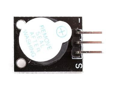
The buzzer activo is an electronic component that produces sound when an electrical signal is applied. It is an active buzzer, meaning it has an internal oscillator and can generate sound on its own when powered, without requiring an external signal generator. This makes it simple to use in a variety of applications.
Explore Projects Built with buzzer activo
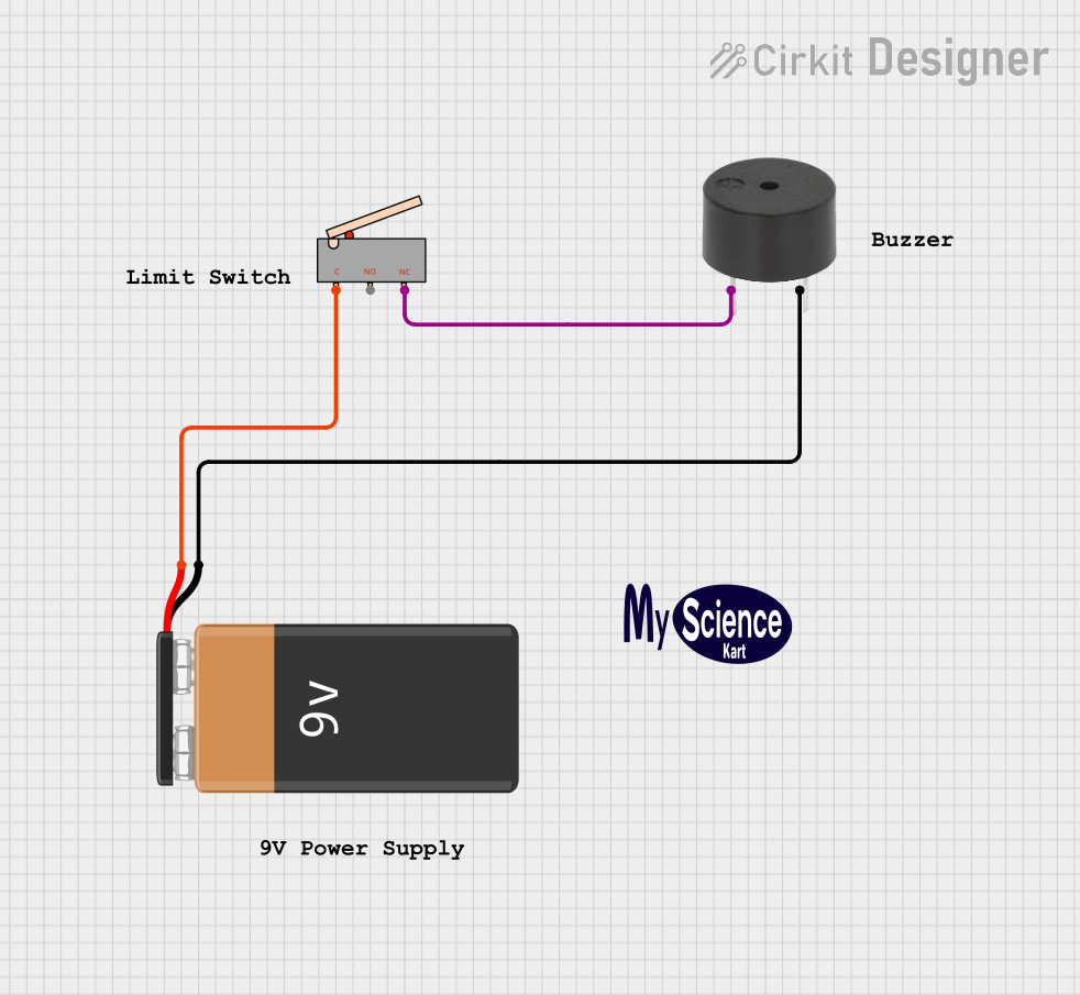
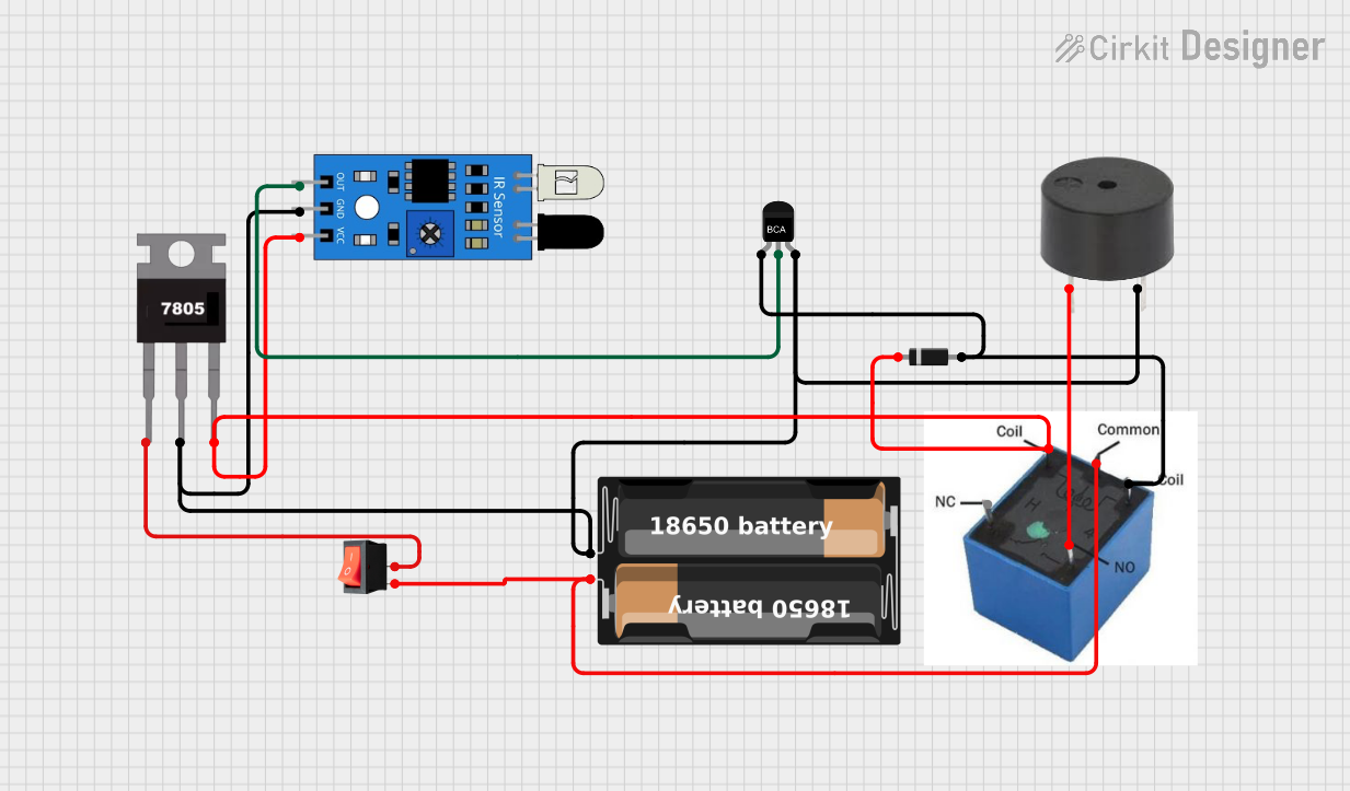
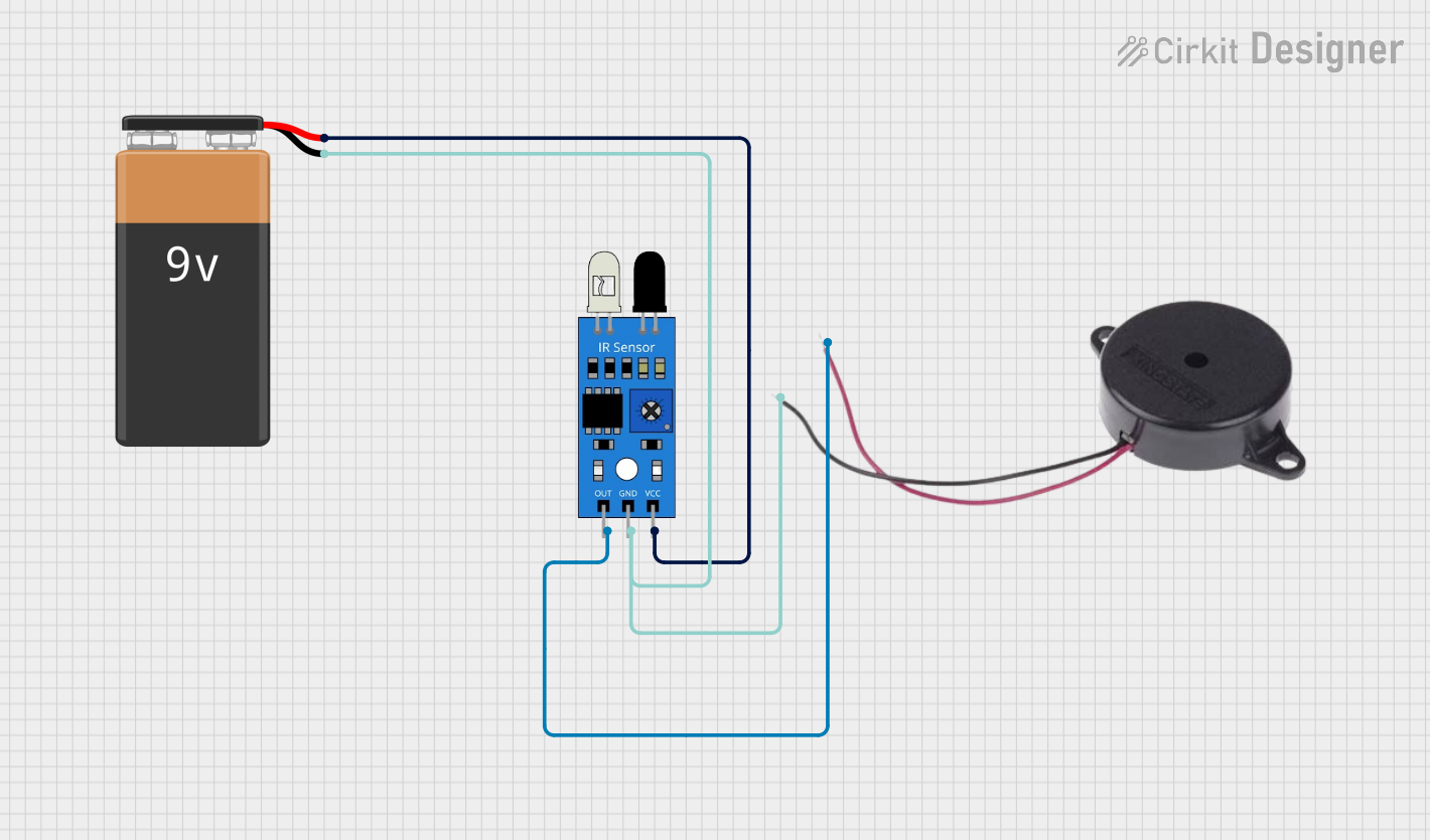
Explore Projects Built with buzzer activo
Common Applications and Use Cases
- Alarms and warning systems
- Timers and reminders
- Notification systems in electronic devices
- Toys and hobby projects
- Arduino-based projects for sound feedback
Technical Specifications
Below are the key technical details of a typical buzzer activo:
| Parameter | Value |
|---|---|
| Operating Voltage | 3V to 12V |
| Rated Voltage | 5V |
| Current Consumption | ≤ 30mA |
| Sound Output Level | 85 dB at 10 cm (typical) |
| Frequency Range | 2 kHz to 4 kHz |
| Operating Temperature | -20°C to +60°C |
| Dimensions | Varies (e.g., 12mm diameter) |
Pin Configuration and Descriptions
The buzzer activo typically has two pins:
| Pin | Description |
|---|---|
| Positive (+) | Connect to the positive terminal of the power supply or microcontroller output. |
| Negative (-) | Connect to the ground (GND) of the circuit. |
Usage Instructions
How to Use the Buzzer Activo in a Circuit
- Power Connection: Connect the positive pin of the buzzer to a power source or a microcontroller's digital output pin. Connect the negative pin to the ground (GND).
- Control with Microcontroller: The buzzer can be controlled using a microcontroller like an Arduino UNO. By sending a HIGH signal to the buzzer's positive pin, it will produce sound.
- Direct Power: Alternatively, the buzzer can be powered directly by a DC voltage source within its operating range (e.g., 5V).
Important Considerations and Best Practices
- Voltage Range: Ensure the supply voltage is within the specified range (3V to 12V). Exceeding this range may damage the buzzer.
- Polarity: Observe correct polarity when connecting the buzzer. Reversing the connections may prevent it from functioning.
- Mounting: Secure the buzzer in place to avoid vibrations affecting its performance.
- Noise Level: The buzzer produces a loud sound, so avoid placing it near sensitive components or in areas where noise is undesirable.
Example: Using the Buzzer Activo with Arduino UNO
Below is an example of how to connect and control the buzzer activo using an Arduino UNO:
Circuit Diagram
- Connect the positive pin of the buzzer to Arduino digital pin 8.
- Connect the negative pin of the buzzer to the Arduino GND.
Code Example
// Buzzer Activo Example with Arduino UNO
// This code makes the buzzer produce sound in a pattern.

const int buzzerPin = 8; // Pin connected to the buzzer

void setup() {
  pinMode(buzzerPin, OUTPUT); // Set the buzzer pin as an output
}

void loop() {
  digitalWrite(buzzerPin, HIGH); // Turn the buzzer ON
  delay(500); // Wait for 500 milliseconds
  digitalWrite(buzzerPin, LOW); // Turn the buzzer OFF
  delay(500); // Wait for 500 milliseconds
}
Explanation of the Code
- The
buzzerPinis set to pin 8, which is connected to the buzzer's positive terminal. - The
setup()function configures the pin as an output. - The
loop()function alternates between turning the buzzer ON and OFF, creating a beeping sound.
Troubleshooting and FAQs
Common Issues and Solutions
No Sound from the Buzzer
- Cause: Incorrect wiring or insufficient voltage.
- Solution: Verify the connections and ensure the supply voltage is within the operating range.
Buzzer Produces Weak or Distorted Sound
- Cause: Low supply voltage or interference from nearby components.
- Solution: Check the power supply and ensure the buzzer is not placed near components that may cause interference.
Buzzer Does Not Turn Off
- Cause: Microcontroller pin is stuck in a HIGH state.
- Solution: Check the code and ensure the pin is set to LOW when the buzzer should be off.
FAQs
Q: Can I use the buzzer activo with a 3.3V microcontroller?
- A: Yes, as long as the buzzer's operating voltage includes 3.3V. Check the datasheet for compatibility.
Q: How loud is the buzzer activo?
- A: The typical sound output level is around 85 dB at 10 cm, but this may vary depending on the model.
Q: Can I control the buzzer's tone or frequency?
- A: No, the buzzer activo has a fixed frequency determined by its internal oscillator. For variable tones, use a passive buzzer.
By following this documentation, you can effectively integrate the buzzer activo into your projects and troubleshoot common issues.