How to Use 433Mhz RF Receiver (with onboard pairing): Examples, Pinouts, and Specs
Introduction
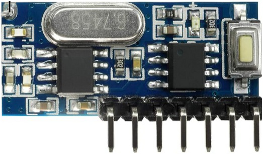
The 433MHz RF Receiver (RX480-E4), manufactured by QIACHIP, is a compact and efficient radio frequency receiver module designed to operate at a frequency of 433 MHz. It is commonly used in wireless communication systems to receive signals from compatible RF transmitters. The module features onboard pairing functionality, enabling secure and straightforward communication setup between devices.
Explore Projects Built with 433Mhz RF Receiver (with onboard pairing)


Explore Projects Built with 433Mhz RF Receiver (with onboard pairing)
Common Applications and Use Cases
- Wireless remote controls (e.g., garage doors, lighting systems)
- Home automation systems
- Internet of Things (IoT) devices
- Wireless data transmission
- Security systems (e.g., alarms, motion detectors)
Technical Specifications
The following table outlines the key technical details of the RX480-E4 module:
| Parameter | Value |
|---|---|
| Operating Frequency | 433 MHz |
| Operating Voltage | 3.3V - 5.5V |
| Operating Current | ≤5 mA |
| Sensitivity | -110 dBm |
| Communication Range | Up to 100 meters (line of sight) |
| Modulation Type | ASK/OOK |
| Data Rate | 2 kbps - 10 kbps |
| Dimensions | 30mm x 14mm x 7mm |
| Operating Temperature | -20°C to +70°C |
Pin Configuration and Descriptions
The RX480-E4 module has a simple pinout for easy integration into circuits. The pin configuration is as follows:
| Pin | Name | Description |
|---|---|---|
| 1 | VCC | Power supply input (3.3V to 5.5V). |
| 2 | GND | Ground connection. |
| 3 | DATA | Digital output pin for received data. Connect to a microcontroller or decoder. |
| 4 | ANT | Antenna connection for receiving RF signals. |
Usage Instructions
How to Use the RX480-E4 in a Circuit
- Power Supply: Connect the VCC pin to a 3.3V or 5V power source and the GND pin to the ground.
- Data Output: Connect the DATA pin to the input pin of a microcontroller (e.g., Arduino) or a decoder IC.
- Antenna: Attach a 17.3 cm wire to the ANT pin to act as an antenna for optimal signal reception.
- Pairing: Use the onboard pairing button to establish a secure connection with a compatible transmitter. Follow the pairing instructions provided by the transmitter's documentation.
Important Considerations and Best Practices
- Antenna Placement: Ensure the antenna is placed away from metal objects or other sources of interference to maximize signal range.
- Power Supply: Use a stable power source to avoid noise or instability in the received signal.
- Decoding Data: The RX480-E4 outputs raw data, which may need to be decoded using a microcontroller or dedicated IC.
- Environmental Factors: The communication range may vary depending on environmental conditions, such as obstacles or interference.
Example: Connecting to an Arduino UNO
Below is an example of how to connect the RX480-E4 to an Arduino UNO and read data from the receiver.
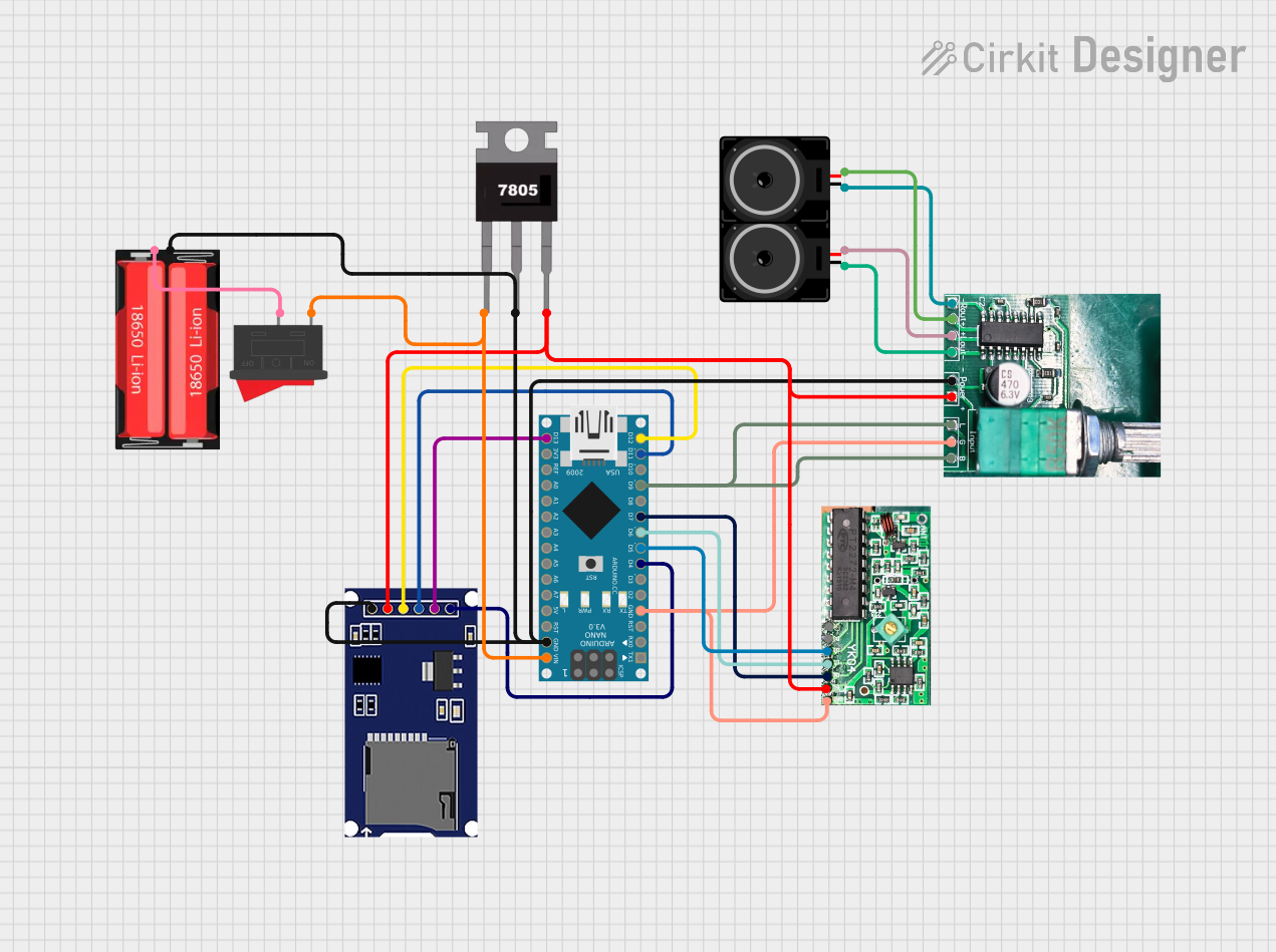
Circuit Diagram
- VCC: Connect to the Arduino's 5V pin.
- GND: Connect to the Arduino's GND pin.
- DATA: Connect to Arduino digital pin 2.
- ANT: Attach a 17.3 cm wire to the ANT pin.
Arduino Code
// Example code to read data from the RX480-E4 433MHz RF Receiver
// Connect the DATA pin of the RX480-E4 to Arduino digital pin 2

#define RF_RECEIVER_PIN 2  // Define the pin connected to the DATA pin of RX480-E4

void setup() {
  Serial.begin(9600);  // Initialize serial communication at 9600 baud
  pinMode(RF_RECEIVER_PIN, INPUT);  // Set the RF receiver pin as input
  Serial.println("433MHz RF Receiver Ready");
}

void loop() {
  int receivedData = digitalRead(RF_RECEIVER_PIN);  // Read data from the receiver
  Serial.print("Received Data: ");
  Serial.println(receivedData);  // Print the received data to the Serial Monitor
  delay(100);  // Add a small delay to avoid flooding the Serial Monitor
}
Troubleshooting and FAQs
Common Issues and Solutions
No Signal Received:
- Ensure the transmitter and receiver are operating at the same frequency (433 MHz).
- Check the antenna connection and ensure it is the correct length (17.3 cm for 433 MHz).
- Verify that the transmitter is powered and functioning correctly.
Unstable or Noisy Data:
- Use a decoupling capacitor (e.g., 0.1 µF) between the VCC and GND pins to stabilize the power supply.
- Ensure the receiver is placed away from sources of electromagnetic interference.
Short Communication Range:
- Check for obstacles or interference in the signal path.
- Use a higher-quality antenna or reposition the receiver for better line-of-sight communication.
Pairing Issues:
- Follow the pairing procedure as outlined in the transmitter's documentation.
- Ensure the receiver is powered on and within range of the transmitter during pairing.
FAQs
Q: Can the RX480-E4 work with other frequencies?
A: No, the RX480-E4 is specifically designed to operate at 433 MHz and is not compatible with other frequencies.
Q: What is the maximum data rate supported by the RX480-E4?
A: The RX480-E4 supports data rates between 2 kbps and 10 kbps.
Q: Can I use the RX480-E4 without an antenna?
A: While the module may work without an antenna, the communication range and signal quality will be significantly reduced. It is recommended to use a 17.3 cm wire as an antenna for optimal performance.
Q: Is the RX480-E4 compatible with Arduino?
A: Yes, the RX480-E4 can be easily interfaced with Arduino or other microcontrollers to process received data.
Q: How do I decode the received data?
A: The RX480-E4 outputs raw digital data, which can be decoded using a microcontroller or a dedicated decoder IC, depending on the protocol used by the transmitter.