How to Use Adafruit STEMMA Non-Latching Relay Breakout: Examples, Pinouts, and Specs
Introduction
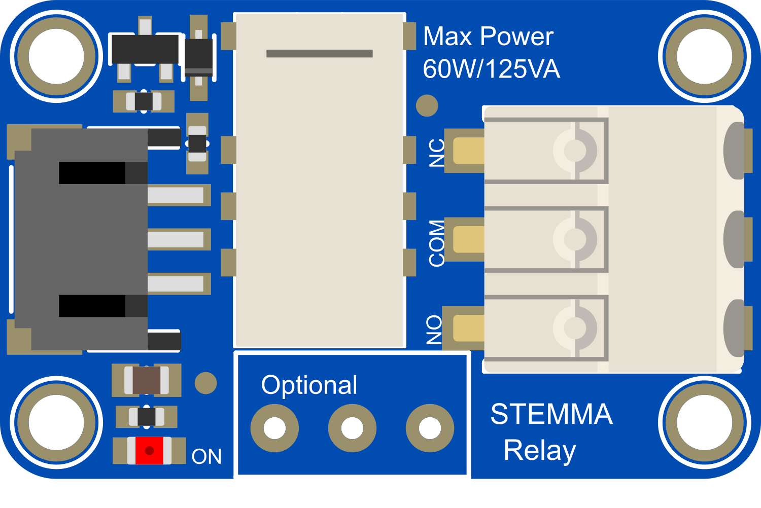
The Adafruit STEMMA Non-Latching Relay Breakout is an essential electronic component designed to interface high-current loads with low-current digital control systems, such as microcontrollers. This breakout board is particularly useful in applications where it is necessary to switch on and off devices that operate at higher voltages and currents than a microcontroller can handle directly. Common applications include home automation, industrial controls, and hobbyist projects where controlling lamps, motors, or other household appliances is required.
Explore Projects Built with Adafruit STEMMA Non-Latching Relay Breakout
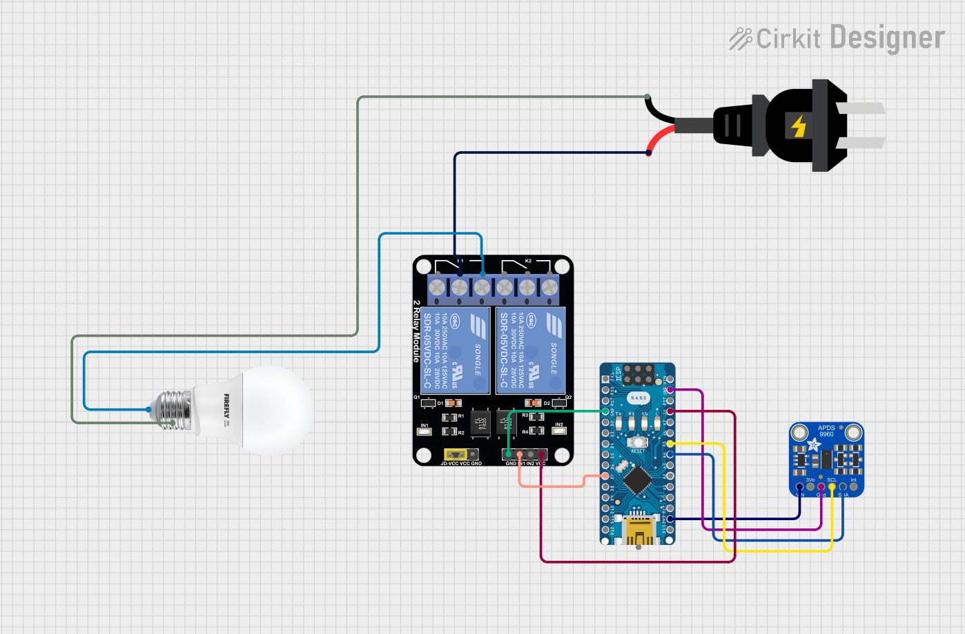
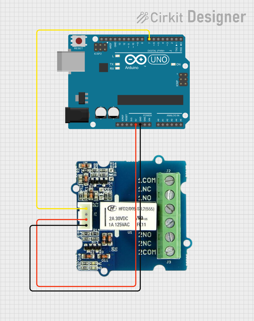
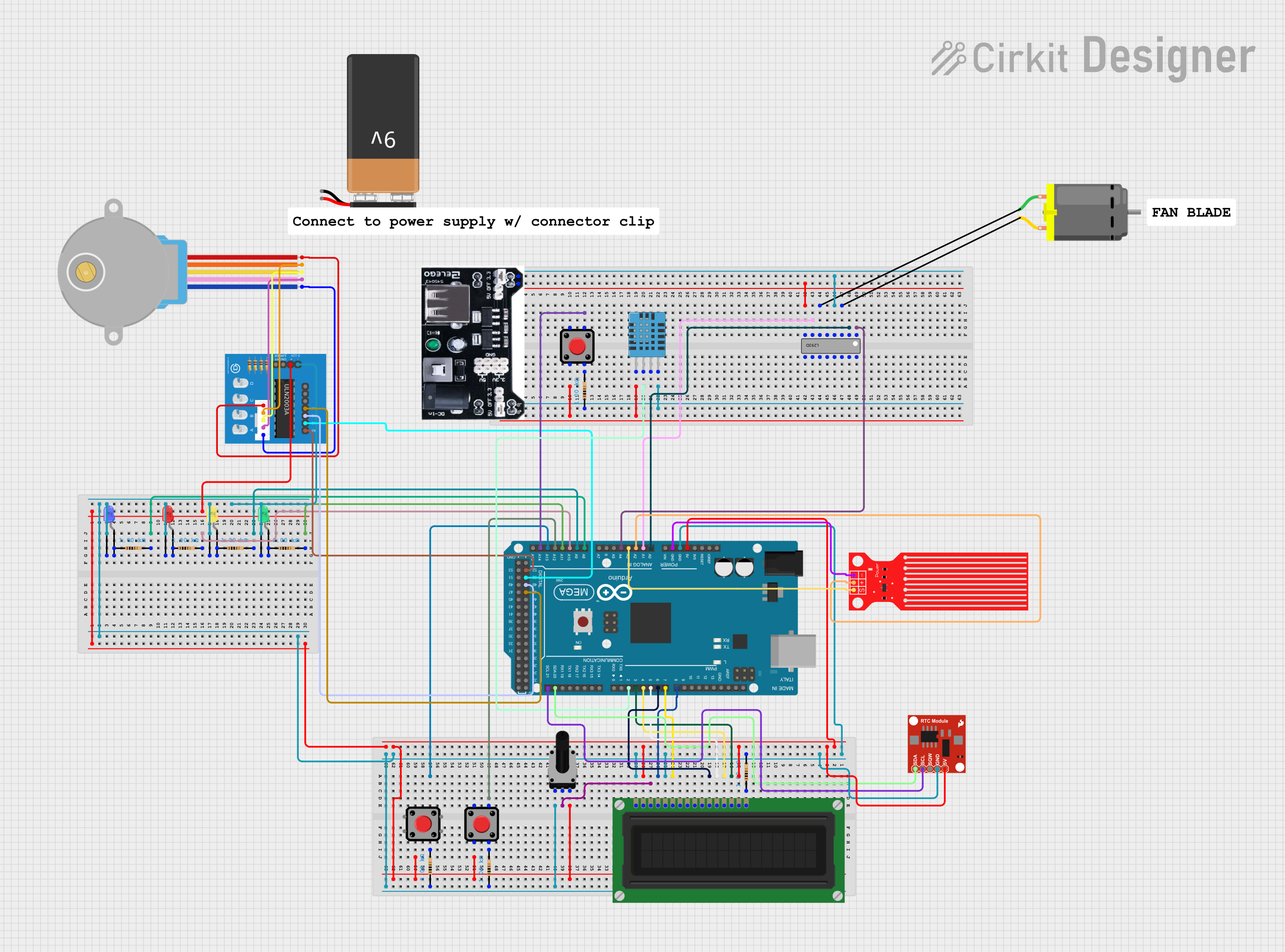
Explore Projects Built with Adafruit STEMMA Non-Latching Relay Breakout
Technical Specifications
Key Technical Details
- Control Voltage: 3.3V to 5V DC
- Switching Current: Maximum 10A
- Switching Voltage: Maximum 250VAC
- Relay Type: Non-latching (single throw)
- Dimensions: 25.4mm x 25.4mm x 19mm
- Weight: 7 grams (approx.)
Pin Configuration and Descriptions
| Pin Name | Description |
|---|---|
| GND | Ground pin, connected to system ground |
| IN | Control input, active high (3.3V to 5V) |
| VCC | Power supply for the relay coil (3.3V to 5V) |
| NO | Normally open contact |
| COM | Common contact |
| NC | Normally closed contact |
Usage Instructions
How to Use the Component in a Circuit
Power Supply Connection:
- Connect the VCC pin to a 3.3V or 5V power supply from your microcontroller.
- Connect the GND pin to the ground of your power supply.
Control Signal:
- Connect the IN pin to a digital output pin on your microcontroller.
Load Connection:
- Connect the device you want to control to the NO (Normally Open) and COM (Common) screw terminals if you want the device to be off when the relay is not activated.
- Alternatively, use the NC (Normally Closed) and COM terminals if you want the device to be on when the relay is not activated.
Important Considerations and Best Practices
- Ensure that the load does not exceed the maximum ratings of the relay (10A at 250VAC).
- Always disconnect power before making or changing connections to the relay.
- Use appropriate wire sizes for the current you are switching.
- If switching inductive loads (like motors), consider using a snubber circuit to protect the relay contacts from voltage spikes.
Example Code for Arduino UNO
// Define the relay control pin
const int relayPin = 2;

void setup() {
  // Set the relay control pin as an output
  pinMode(relayPin, OUTPUT);
}

void loop() {
  // Turn on the relay (close NO contact)
  digitalWrite(relayPin, HIGH);
  delay(1000); // Wait for 1 second

  // Turn off the relay (open NO contact)
  digitalWrite(relayPin, LOW);
  delay(1000); // Wait for 1 second
}
Troubleshooting and FAQs
Common Issues
- Relay does not switch: Check the control signal voltage and connections. Ensure that the IN pin receives a high signal (3.3V to 5V).
- Load does not turn on/off: Verify that the load is properly connected to the NO/NC and COM terminals and that it does not exceed the relay's maximum ratings.
Solutions and Tips for Troubleshooting
- Use a multimeter to check for continuity across the relay contacts when activated.
- If using long wires or cables, ensure they are properly shielded to prevent noise from affecting the control signal.
- Always provide a sufficient power supply that can handle the relay's coil current without voltage drops.
FAQs
Q: Can I use this relay with a 3.3V microcontroller? A: Yes, the relay can be controlled with a 3.3V logic level.
Q: Is it safe to switch AC loads with this relay? A: Yes, as long as the load does not exceed 10A at 250VAC.
Q: What is the difference between a non-latching and a latching relay? A: A non-latching relay requires continuous power to maintain its state, while a latching relay maintains its state without power once switched.
Q: Can I control this relay with PWM? A: No, PWM is not suitable for controlling relays. Use a digital HIGH or LOW signal to control the relay state.
For further assistance, please refer to the Adafruit support forums or contact technical support.