How to Use Mini Boost Converter HW-085 1.5A - 5/8/9/12V Fixed: Examples, Pinouts, and Specs
Introduction
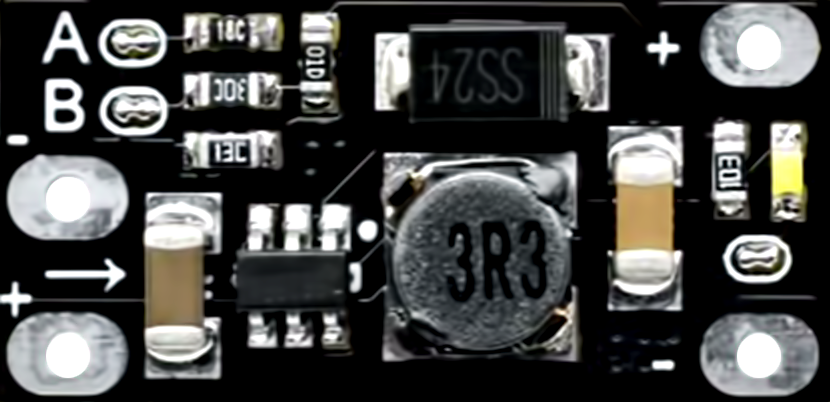
The Mini Boost Converter HW-085 is a compact DC-DC step-up module designed to increase a lower input voltage to a fixed higher output voltage. It supports four fixed output voltage levels: 5V, 8V, 9V, and 12V, selectable via a jumper. With a maximum output current of 1.5A, this module is ideal for powering devices that require a higher voltage than the input source can provide. Its small size and efficiency make it suitable for portable electronics, battery-powered projects, and DIY applications.
Explore Projects Built with Mini Boost Converter HW-085 1.5A - 5/8/9/12V Fixed


Explore Projects Built with Mini Boost Converter HW-085 1.5A - 5/8/9/12V Fixed
Common Applications
- Powering microcontrollers, sensors, and modules from a lower voltage source
- Boosting voltage from batteries (e.g., 3.7V Li-ion or 1.5V AA cells)
- DIY electronics projects requiring compact power solutions
- Portable devices and USB-powered gadgets
Technical Specifications
Key Technical Details
| Parameter | Value |
|---|---|
| Input Voltage Range | 2V to 24V |
| Output Voltage Options | 5V, 8V, 9V, 12V (selectable via jumper) |
| Maximum Output Current | 1.5A (varies with input voltage) |
| Efficiency | Up to 93% (depending on input/output load) |
| Dimensions | 30mm x 17mm x 14mm |
| Weight | ~5g |
Pin Configuration and Descriptions
| Pin Name | Description |
|---|---|
| VIN | Positive input voltage terminal (2V to 24V) |
| GND | Ground terminal (common ground for input and output) |
| VOUT | Positive output voltage terminal (fixed at 5V, 8V, 9V, or 12V, as selected) |
Jumper Configuration
| Jumper Position | Output Voltage |
|---|---|
| Short 5V | 5V |
| Short 8V | 8V |
| Short 9V | 9V |
| Short 12V | 12V |
Usage Instructions
How to Use the Mini Boost Converter HW-085
Connect the Input Voltage:
- Connect the positive terminal of your power source to the
VINpin. - Connect the negative terminal of your power source to the
GNDpin. - Ensure the input voltage is within the range of 2V to 24V.
- Connect the positive terminal of your power source to the
Set the Desired Output Voltage:
- Use the onboard jumper to select the desired output voltage (5V, 8V, 9V, or 12V).
- Ensure the jumper is securely placed in the correct position.
Connect the Load:
- Connect the positive terminal of your load to the
VOUTpin. - Connect the negative terminal of your load to the
GNDpin.
- Connect the positive terminal of your load to the
Power On:
- Turn on the input power source. The module will step up the input voltage to the selected output voltage.
Important Considerations and Best Practices
- Input Voltage Range: Ensure the input voltage is within the specified range (2V to 24V). Exceeding this range may damage the module.
- Output Current Limit: The maximum output current is 1.5A, but it may vary depending on the input voltage and load. Avoid overloading the module.
- Heat Dissipation: At higher loads, the module may generate heat. Ensure adequate ventilation or consider adding a heatsink if necessary.
- Polarity Protection: The module does not have reverse polarity protection. Double-check connections before powering on.
- Noise Filtering: If using the module in sensitive circuits, consider adding capacitors at the input and output to reduce noise.
Example: Using with an Arduino UNO
The Mini Boost Converter HW-085 can be used to power an Arduino UNO from a 3.7V Li-ion battery by stepping up the voltage to 5V.
Circuit Connection
- Connect the battery's positive terminal to
VINand negative terminal toGND. - Set the jumper to the 5V position.
- Connect the
VOUTpin to the Arduino's 5V pin andGNDto the Arduino's GND pin.
Sample Code
// Example code to blink an LED connected to Arduino UNO
// Ensure the Mini Boost Converter is providing 5V to the Arduino

void setup() {
  pinMode(13, OUTPUT); // Set pin 13 as an output for the onboard LED
}

void loop() {
  digitalWrite(13, HIGH); // Turn the LED on
  delay(1000);            // Wait for 1 second
  digitalWrite(13, LOW);  // Turn the LED off
  delay(1000);            // Wait for 1 second
}
Troubleshooting and FAQs
Common Issues and Solutions
No Output Voltage:
- Cause: Incorrect jumper configuration or loose connections.
- Solution: Verify the jumper is set to the desired output voltage and check all connections.
Output Voltage is Incorrect:
- Cause: Input voltage is too low or jumper is in the wrong position.
- Solution: Ensure the input voltage is within the specified range and recheck the jumper setting.
Module Overheats:
- Cause: Excessive load or poor ventilation.
- Solution: Reduce the load current or improve ventilation around the module.
Load Does Not Power On:
- Cause: Load requires more current than the module can provide.
- Solution: Ensure the load's current requirement is within the module's 1.5A limit.
FAQs
Q1: Can I use this module to charge a battery?
A1: No, this module is not designed for battery charging. It is a step-up converter for powering devices.
Q2: What happens if I reverse the input polarity?
A2: The module does not have reverse polarity protection and may be damaged. Always double-check connections.
Q3: Can I adjust the output voltage to a custom value?
A3: No, the output voltage is fixed to 5V, 8V, 9V, or 12V, as selected by the jumper.
Q4: Is the module suitable for audio applications?
A4: The module may introduce noise, so additional filtering may be required for sensitive audio circuits.