How to Use Adafruit Circuit Playground Dev Edition: Examples, Pinouts, and Specs
Introduction
The Adafruit Circuit Playground Developer Edition is an all-in-one circuit development board that is ideal for beginners and experts alike. It is designed to provide a platform for learning electronics and coding without the need for breadboarding or soldering. The board comes with a variety of built-in sensors, input/output devices, and LEDs, making it highly versatile for a wide range of projects, from simple LED blink programs to more complex sensor-based interactions.
Explore Projects Built with Adafruit Circuit Playground Dev Edition
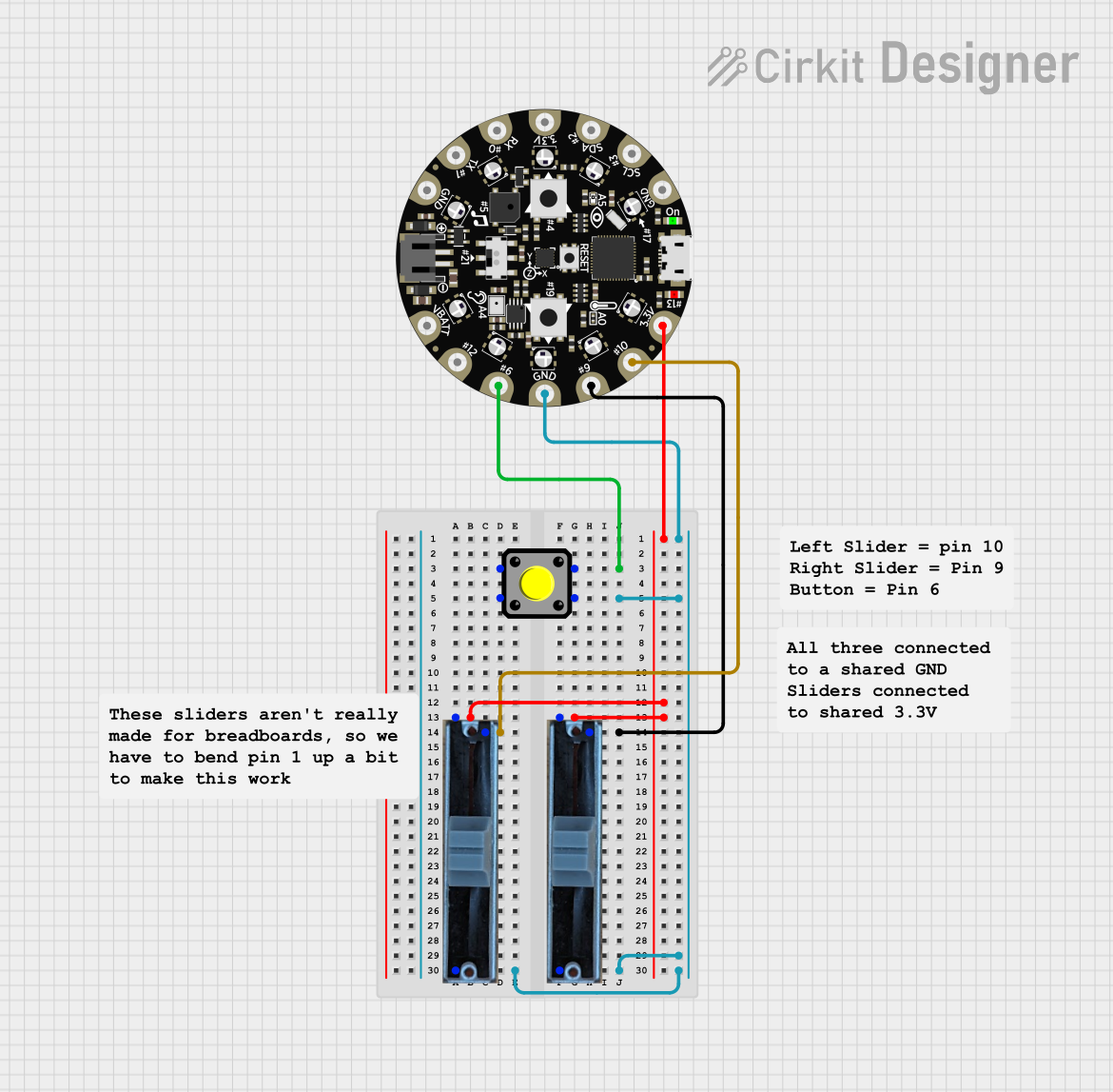
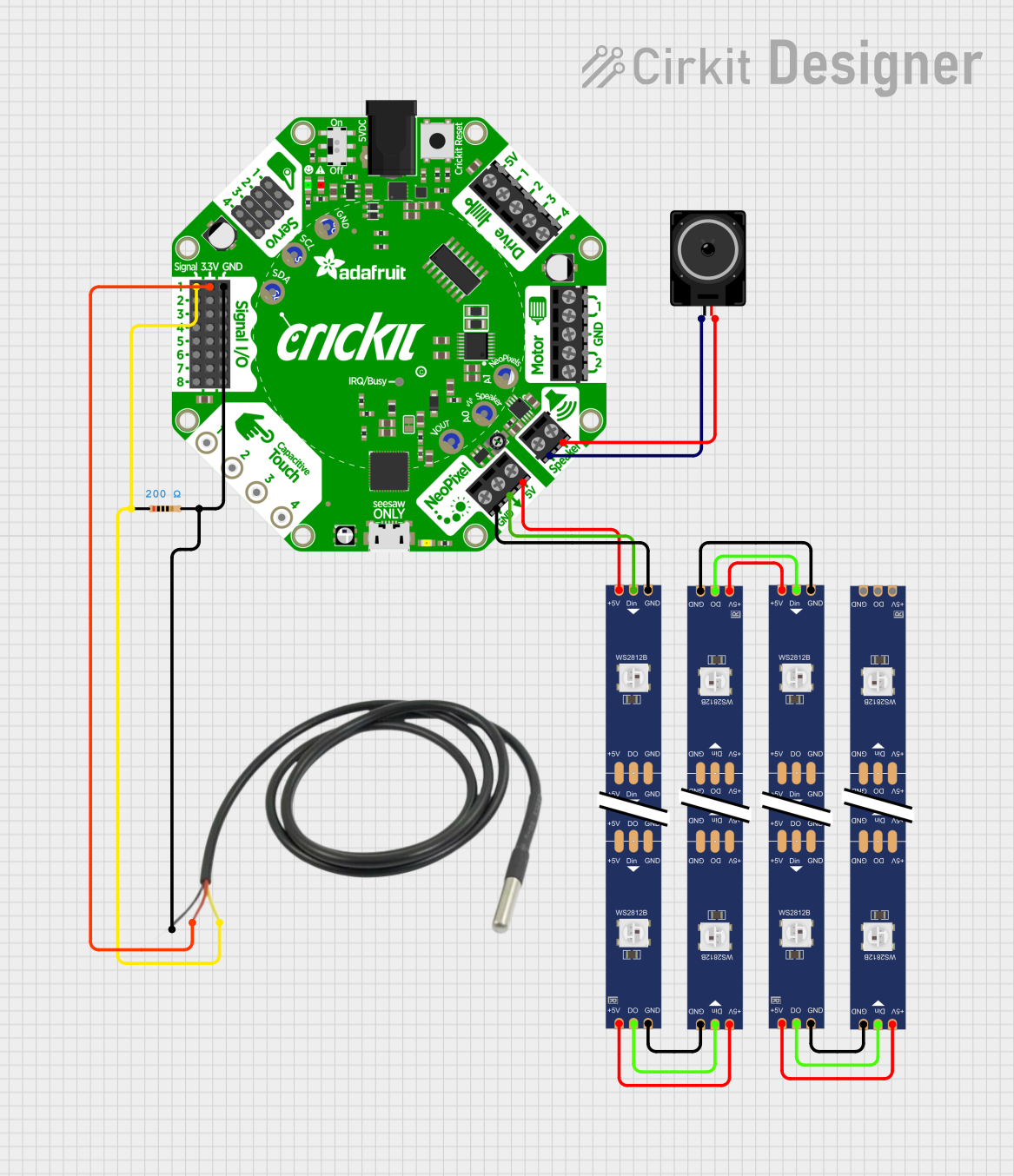
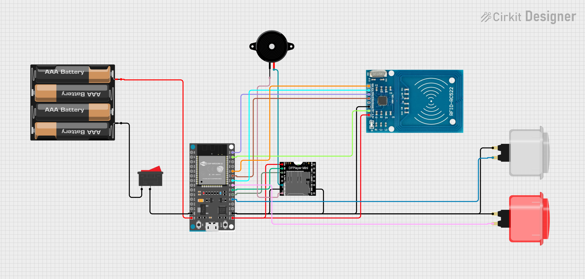
Explore Projects Built with Adafruit Circuit Playground Dev Edition
Common Applications and Use Cases
- Educational purposes (e.g., teaching programming and electronics)
- Prototyping wearable electronics
- Interactive art installations
- DIY projects and hobbies
- Rapid prototyping of sensor-based systems
Technical Specifications
Key Technical Details
- Microcontroller: ATmega32u4
- Operating Voltage: 3.3V
- Input Voltage (recommended): 4-6V via battery port
- Digital I/O Pins: 10
- PWM Channels: 4
- Analog Input Channels: 8
- DC Current per I/O Pin: 40 mA
- Flash Memory: 32 KB (ATmega32u4) of which 4 KB used by bootloader
- SRAM: 2.5 KB (ATmega32u4)
- EEPROM: 1 KB (ATmega32u4)
- Clock Speed: 8 MHz
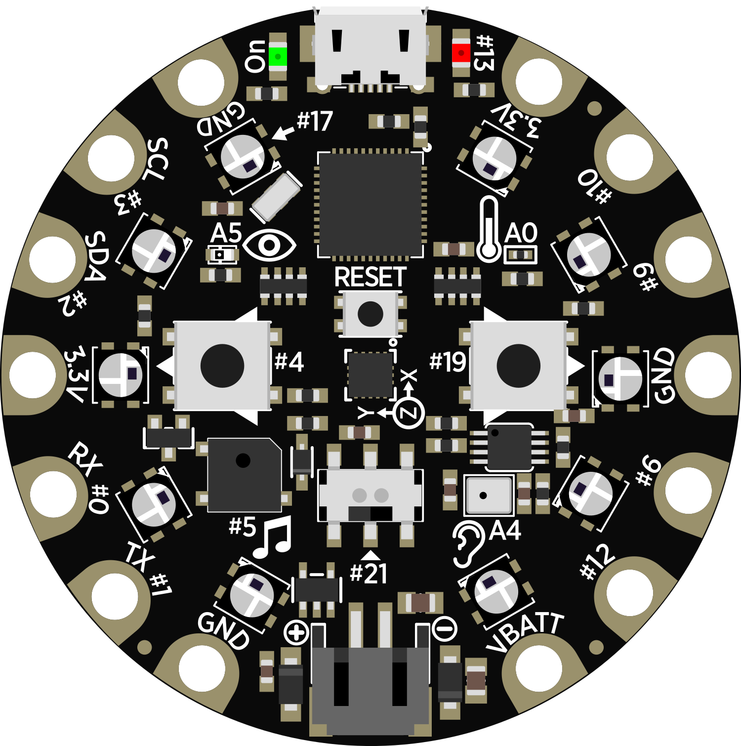
Pin Configuration and Descriptions
| Pin Number | Function | Description |
|---|---|---|
| 1 | RESET | Reset pin, active low |
| 2-7 | Digital I/O | Digital pins, can be used as input or output |
| 8-9 | Analog Input | Analog sensor inputs |
| 10 | VBAT | Battery input for power |
| 11 | GND | Ground |
| 12 | 3.3V | 3.3V power supply pin |
| 13 | AREF | Analog reference voltage for the ADC |
| 14 | SCL | I2C clock pin |
| 15 | SDA | I2C data pin |
| 16 | RX | UART receive pin |
| 17 | TX | UART transmit pin |
Usage Instructions
How to Use the Component in a Circuit
Powering the Board:
- Connect a battery to the VBAT and GND pins, or use the USB connection to power the board.
Programming the Board:
- Connect the board to a computer using a micro USB cable.
- Use the Arduino IDE or other compatible software to write and upload your code.
Interacting with Onboard Features:
- Utilize the built-in sensors and LEDs in your code to create interactive projects.
Important Considerations and Best Practices
- Always ensure that the power supply voltage is within the recommended range to prevent damage.
- When connecting external components, make sure they are compatible with the board's operating voltage.
- Avoid drawing more current than the maximum specified for each I/O pin.
- Use proper static handling procedures to avoid damaging the board's sensitive components.
Troubleshooting and FAQs
Common Issues Users Might Face
Board Not Recognized by Computer:
- Ensure the micro USB cable is properly connected and the computer's USB port is functioning.
- Try using a different USB cable or port.
Problems Uploading Code:
- Check that the correct board and port are selected in the Arduino IDE.
- Press the reset button on the board just before uploading if the upload fails.
Solutions and Tips for Troubleshooting
- If the onboard LEDs do not light up, verify the board's power supply and connections.
- For sensor-related issues, calibrate the sensors according to the datasheets and ensure that the code is correctly reading the sensor values.
FAQs
Q: Can I power the board using a 9V battery?
- A: It is not recommended to directly connect a 9V battery to the VBAT pin as it exceeds the recommended input voltage.
Q: How do I use the onboard microphone and speaker?
- A: The microphone can be accessed via the analog input pins, and the speaker can be controlled using one of the PWM-capable digital pins.
Example Code for Arduino UNO
Below is a simple example code that blinks the onboard LED on the Circuit Playground Developer Edition. This code is written for use with the Arduino IDE.
// Blink the onboard LED

void setup() {
  // Initialize the onboard LED pin as an output.
  pinMode(13, OUTPUT);
}

void loop() {
  // Turn the LED on (HIGH is the voltage level)
  digitalWrite(13, HIGH);
  // Wait for a second
  delay(1000);
  // Turn the LED off by making the voltage LOW
  digitalWrite(13, LOW);
   // Wait for a second
  delay(1000);
}
Remember to select the correct board from the Tools > Board menu in the Arduino IDE before uploading the code to the Adafruit Circuit Playground Developer Edition.