Cirkit Designer Logo
Cirkit Designer
Your all-in-one circuit design IDE
Home / 
Component Documentation

How to Use Grove - RS485 : Examples, Pinouts, and Specs

Image of Grove - RS485
Cirkit Designer LogoDesign with Grove - RS485 in Cirkit Designer

Introduction

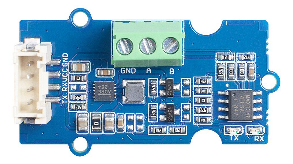
The Grove - RS485 (Manufacturer Part ID: 103020193) is a communication module designed by Seeed Studio. It enables long-distance, robust, and noise-resistant serial communication using the RS485 protocol. RS485 is widely used in industrial and commercial applications due to its ability to support multiple devices on the same bus and its resilience in noisy environments.

Explore Projects Built with Grove - RS485

Use Cirkit Designer to design, explore, and prototype these projects online. Some projects support real-time simulation. Click "Open Project" to start designing instantly!
RS485-Enabled NPK Soil Sensor Interface
Image of NPK: A project utilizing Grove - RS485  in a practical application
This circuit connects an NPK Soil Sensor to an RS485 transceiver module. The sensor's VCC and GND pins are connected to the corresponding VCC and GND pins on the RS485 module to provide power. The sensor's analog output (A) and digital output (B) are interfaced with the RS485 module's DI (Data Input) and DE (Driver Enable) pins, respectively, allowing the sensor's signals to be transmitted over an RS485 communication bus.
Cirkit Designer LogoOpen Project in Cirkit Designer
ESP32C3-Based Soil Monitoring System with RS485 Communication
Image of 3-slave-soil: A project utilizing Grove - RS485  in a practical application
This circuit features an ESP32C3 Supermini microcontroller interfaced with an RS485 transceiver module, allowing for serial communication over long distances. A toggle switch and a pushbutton are connected to the ESP32C3 for user input, with a pull-up resistor on the toggle switch. Additionally, the circuit includes an NPK Soil Sensor connected to the RS485 module for measuring soil nutrient levels, with power supplied to the sensor and RS485 module from the ESP32C3.
Cirkit Designer LogoOpen Project in Cirkit Designer
STM32 and Arduino UNO Based Dual RS485 Communication Interface
Image of STM to Arduino RS485: A project utilizing Grove - RS485  in a practical application
This circuit consists of two microcontrollers, an STM32F103C8T6 and an Arduino UNO, each interfaced with separate RS485 transceiver modules for serial communication. The STM32F103C8T6 controls the RE (Receiver Enable) and DE (Driver Enable) pins of one RS485 module to manage its operation, and communicates via the A9 and A10 pins for DI (Data Input) and RO (Receiver Output), respectively. The Arduino UNO is similarly connected to another RS485 module, with digital pins D2 and D3 interfacing with DI and RO, and D8 controlling both RE and DE. The RS485 modules are connected to each other through their A and B differential communication lines, enabling serial data exchange between the two microcontrollers over a robust and long-distance capable RS485 network.
Cirkit Designer LogoOpen Project in Cirkit Designer
Arduino UNO and Relay-Controlled RS485 Communication System
Image of Diagrama: A project utilizing Grove - RS485  in a practical application
This circuit features an Arduino UNO microcontroller interfaced with a 4-channel relay module and a UART TTL to RS485 converter. The Arduino controls the relays via digital pins and communicates with the RS485 converter for serial communication, enabling control of external devices and communication over long distances.
Cirkit Designer LogoOpen Project in Cirkit Designer

Explore Projects Built with Grove - RS485

Use Cirkit Designer to design, explore, and prototype these projects online. Some projects support real-time simulation. Click "Open Project" to start designing instantly!
Image of NPK: A project utilizing Grove - RS485  in a practical application
RS485-Enabled NPK Soil Sensor Interface
This circuit connects an NPK Soil Sensor to an RS485 transceiver module. The sensor's VCC and GND pins are connected to the corresponding VCC and GND pins on the RS485 module to provide power. The sensor's analog output (A) and digital output (B) are interfaced with the RS485 module's DI (Data Input) and DE (Driver Enable) pins, respectively, allowing the sensor's signals to be transmitted over an RS485 communication bus.
Cirkit Designer LogoOpen Project in Cirkit Designer
Image of 3-slave-soil: A project utilizing Grove - RS485  in a practical application
ESP32C3-Based Soil Monitoring System with RS485 Communication
This circuit features an ESP32C3 Supermini microcontroller interfaced with an RS485 transceiver module, allowing for serial communication over long distances. A toggle switch and a pushbutton are connected to the ESP32C3 for user input, with a pull-up resistor on the toggle switch. Additionally, the circuit includes an NPK Soil Sensor connected to the RS485 module for measuring soil nutrient levels, with power supplied to the sensor and RS485 module from the ESP32C3.
Cirkit Designer LogoOpen Project in Cirkit Designer
Image of STM to Arduino RS485: A project utilizing Grove - RS485  in a practical application
STM32 and Arduino UNO Based Dual RS485 Communication Interface
This circuit consists of two microcontrollers, an STM32F103C8T6 and an Arduino UNO, each interfaced with separate RS485 transceiver modules for serial communication. The STM32F103C8T6 controls the RE (Receiver Enable) and DE (Driver Enable) pins of one RS485 module to manage its operation, and communicates via the A9 and A10 pins for DI (Data Input) and RO (Receiver Output), respectively. The Arduino UNO is similarly connected to another RS485 module, with digital pins D2 and D3 interfacing with DI and RO, and D8 controlling both RE and DE. The RS485 modules are connected to each other through their A and B differential communication lines, enabling serial data exchange between the two microcontrollers over a robust and long-distance capable RS485 network.
Cirkit Designer LogoOpen Project in Cirkit Designer
Image of Diagrama: A project utilizing Grove - RS485  in a practical application
Arduino UNO and Relay-Controlled RS485 Communication System
This circuit features an Arduino UNO microcontroller interfaced with a 4-channel relay module and a UART TTL to RS485 converter. The Arduino controls the relays via digital pins and communicates with the RS485 converter for serial communication, enabling control of external devices and communication over long distances.
Cirkit Designer LogoOpen Project in Cirkit Designer

Common Applications and Use Cases

  • Industrial automation and control systems
  • Building management systems (e.g., HVAC, lighting control)
  • Long-distance data communication
  • Multi-device communication on a single bus
  • Applications requiring noise-resistant communication

Technical Specifications

The following table outlines the key technical details of the Grove - RS485 module:

Parameter Value
Communication Protocol RS485
Operating Voltage 3.3V / 5V
Baud Rate Up to 115200 bps
Operating Temperature -40°C to 85°C
Dimensions 40mm x 20mm
Connector Type Grove 4-pin interface

Pin Configuration and Descriptions

The Grove - RS485 module uses a 4-pin Grove connector. The pinout is as follows:

Pin Name Description
1 VCC Power supply input (3.3V or 5V)
2 GND Ground
3 RX UART Receive (connect to TX of the microcontroller)
4 TX UART Transmit (connect to RX of the microcontroller)

Usage Instructions

How to Use the Grove - RS485 in a Circuit

  1. Connect the Module:

    • Use a Grove cable to connect the Grove - RS485 module to a compatible Grove Base Shield or Grove port on your microcontroller (e.g., Arduino UNO).
    • Ensure the VCC pin matches the operating voltage of your microcontroller (3.3V or 5V).
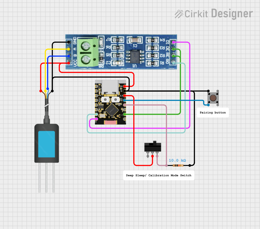
  2. Wiring for RS485 Communication:

    • Connect the A and B terminals of the RS485 bus to the corresponding A and B terminals of the Grove - RS485 module.
    • If multiple devices are on the same RS485 bus, ensure proper termination resistors are used at both ends of the bus.
  3. Configure the Microcontroller:

    • Set up the UART interface on your microcontroller to communicate with the Grove - RS485 module.
    • Use the appropriate baud rate (e.g., 9600 bps or 115200 bps) as required by your application.
  4. Write and Upload Code:

    • Use the following example code to test communication with the Grove - RS485 module using an Arduino UNO.

Example Code for Arduino UNO

#include <SoftwareSerial.h>

// Define RX and TX pins for SoftwareSerial
#define RX_PIN 2  // Connect to TX of Grove - RS485
#define TX_PIN 3  // Connect to RX of Grove - RS485

// Initialize SoftwareSerial
SoftwareSerial RS485Serial(RX_PIN, TX_PIN);

void setup() {
  // Start the hardware serial port for debugging
  Serial.begin(9600);
  while (!Serial) {
    ; // Wait for the serial port to connect
  }
  Serial.println("Grove - RS485 Test");

  // Start the RS485 serial communication
  RS485Serial.begin(9600);
}

void loop() {
  // Send a message via RS485
  RS485Serial.println("Hello, RS485!");

  // Check if data is available from RS485
  if (RS485Serial.available()) {
    String receivedData = RS485Serial.readString();
    Serial.print("Received via RS485: ");
    Serial.println(receivedData);
  }

  delay(1000); // Wait for 1 second before sending the next message
}

Important Considerations and Best Practices

  • Termination Resistors: Use 120-ohm termination resistors at both ends of the RS485 bus to prevent signal reflections.
  • Grounding: Ensure all devices on the RS485 bus share a common ground to avoid communication issues.
  • Baud Rate Matching: Ensure all devices on the RS485 bus are configured to use the same baud rate.
  • Cable Selection: Use twisted-pair cables for long-distance communication to minimize noise interference.

Troubleshooting and FAQs

Common Issues and Solutions

  1. No Communication Between Devices:

    • Verify the A and B terminals are correctly connected.
    • Check that all devices on the RS485 bus share a common ground.
    • Ensure the baud rate is the same for all devices.
  2. Data Corruption or Noise:

    • Use shielded or twisted-pair cables to reduce noise.
    • Add termination resistors (120 ohms) at both ends of the RS485 bus.
  3. Module Not Responding:

    • Confirm the Grove cable is securely connected.
    • Check the power supply voltage (3.3V or 5V) matches the module's requirements.

FAQs

Q: Can I connect multiple Grove - RS485 modules to the same RS485 bus?
A: Yes, RS485 supports multi-device communication. Ensure each device has a unique address or identifier in your application.

Q: What is the maximum communication distance for RS485?
A: RS485 can communicate over distances up to 1200 meters (4000 feet) with proper cabling and termination.

Q: Can I use the Grove - RS485 module with a 3.3V microcontroller?
A: Yes, the module supports both 3.3V and 5V operating voltages, making it compatible with a wide range of microcontrollers.

Q: Do I need to install any libraries to use the Grove - RS485 with Arduino?
A: No additional libraries are required if you use the built-in SoftwareSerial library for UART communication.