How to Use Adafruit Feather STM32F405: Examples, Pinouts, and Specs
Introduction
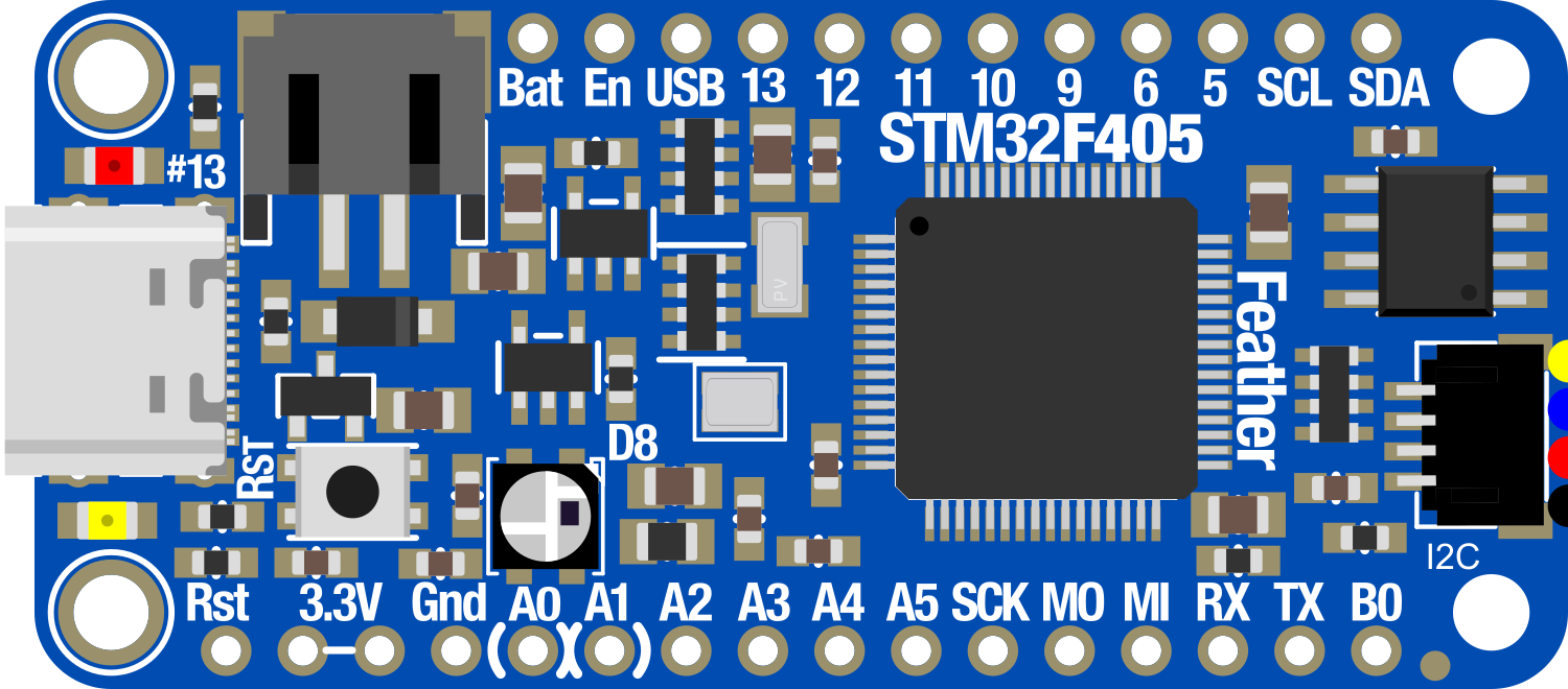
The Adafruit Feather STM32F405 is a versatile and powerful microcontroller board designed for advanced hobbyists and professionals alike. It leverages the capabilities of the STM32F405 microcontroller, featuring a Cortex-M4 core with a maximum clock speed of 168MHz. This board is ideal for projects that require significant processing power, such as complex robotics, precision sensors, and advanced data logging. With built-in USB connectivity, a microSD card slot, and motion sensors, the Feather STM32F405 is a comprehensive solution for a wide range of applications.
Common applications include:
- High-speed data acquisition
- Robotics and automation
- Wearable devices
- Flight controllers for drones
- Advanced DIY projects with motion sensing
Explore Projects Built with Adafruit Feather STM32F405
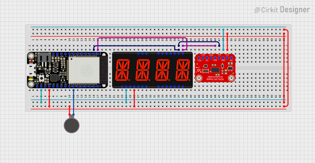
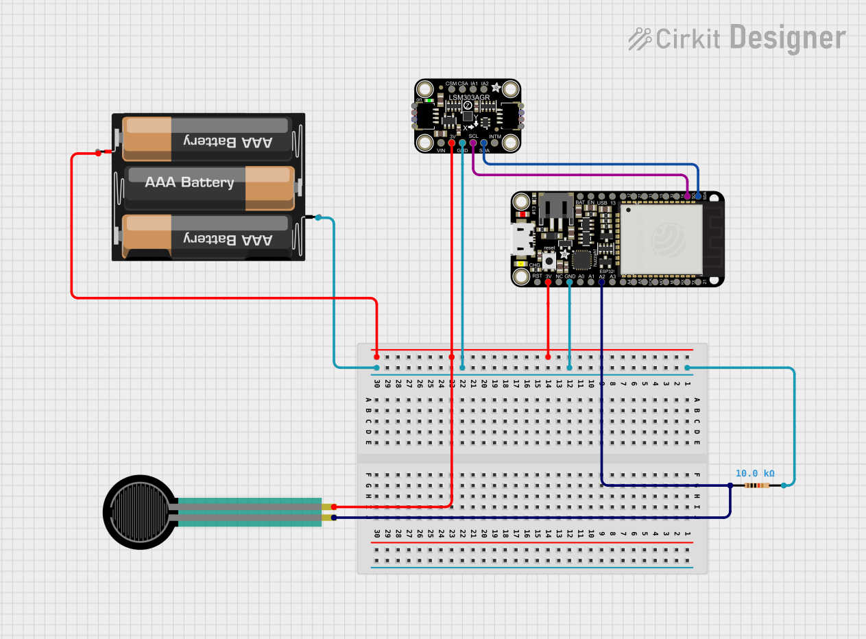
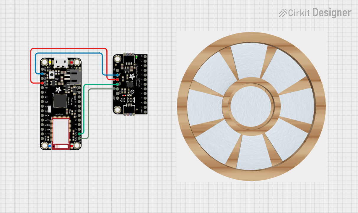

Explore Projects Built with Adafruit Feather STM32F405
Technical Specifications
Key Technical Details
- Microcontroller: STM32F405RG
- Core: Cortex-M4
- Clock Speed: 168 MHz
- Operating Voltage: 3.3V
- Input Voltage: 5V via USB or 3.7-6V via battery
- Digital I/O Pins: 20
- Analog Input Pins: 6
- Flash Memory: 1 MB
- SRAM: 192 KB
- Interfaces: I2C, SPI, UART
- USB: Micro-USB for programming and power
- Sensors: LSM6DSOX (accelerometer and gyro)
- Storage: microSD card slot
Pin Configuration and Descriptions
| Pin Number | Function | Description |
|---|---|---|
| 1 | VIN | Input voltage for battery (3.7-6V) |
| 2 | GND | Ground |
| 3-8 | Digital I/O | General-purpose input/output |
| 9 | AREF | Analog reference voltage |
| 10-15 | Analog Input | Analog input channels |
| 16 | 3V3 | 3.3V output from the regulator |
| 17 | RST | Reset pin |
| 18-19 | I2C (SCL, SDA) | I2C communication lines |
| 20-21 | SPI (SCK, MISO, MOSI) | SPI communication lines |
| 22-23 | UART (RX, TX) | UART communication lines |
| 24 | USB D+ | USB data plus |
| 25 | USB D- | USB data minus |
Usage Instructions
Integrating with a Circuit
To use the Adafruit Feather STM32F405 in a circuit:
- Connect the board to a power source, either through the USB port or by attaching a battery to the VIN pin.
- Interface with sensors, actuators, or other peripherals using the digital I/O, analog inputs, or communication interfaces (I2C, SPI, UART).
- Ensure that the connected components are compatible with the board's operating voltage (3.3V).
Programming with Arduino IDE
- Install the Arduino IDE and the necessary board support package for the STM32F405.
- Connect the Feather STM32F405 to your computer using a micro-USB cable.
- Select the correct board and port in the Arduino IDE.
- Write or upload your sketch to the board.
Best Practices
- Always disconnect the board from power sources before making or altering connections.
- Use a logic level converter if interfacing with 5V components to prevent damage to the board.
- Avoid exposing the board to static electricity or physical stress.
Troubleshooting and FAQs
Common Issues
- Board not recognized by the computer: Ensure the micro-USB cable is properly connected and functioning. Try a different cable or port if necessary.
- Sketch not uploading: Check that the correct board and port are selected in the Arduino IDE. Press the reset button on the board and try uploading again.
- Interfacing issues with peripherals: Verify that all connections are secure and that the peripherals are powered correctly.
FAQs
Can I power the Feather STM32F405 with a 5V supply? Yes, through the USB port or a regulated 5V supply to the VIN pin.
Is the Feather STM32F405 compatible with all Arduino shields? Not all shields are directly compatible due to voltage and pinout differences. Check the shield specifications and use a logic level converter if necessary.
How do I use the onboard accelerometer and gyro? You can access the LSM6DSOX sensor using the appropriate libraries and communicate via the I2C interface.
For further assistance, consult the Adafruit support forums or the extensive online documentation available for the STM32F405 microcontroller.
Example Code for Arduino UNO
// Example code to read from the onboard accelerometer and gyro
#include <Wire.h>
#include <Adafruit_LSM6DSOX.h>

Adafruit_LSM6DSOX sox;

void setup() {
  Serial.begin(115200);
  // Wait for serial monitor to open
  while (!Serial) { delay(10); }

  Serial.println("LSM6DSOX test!");

  if (!sox.begin_I2C()) { // Use default I2C port, 400kHz
    Serial.println("Failed to find LSM6DSOX chip");
    while (1) {
      delay(10);
    }
  }
  Serial.println("LSM6DSOX Found!");
}

void loop() {
  // Read from the sensor
  sensors_event_t accel;
  sensors_event_t gyro;
  sensors_event_t temp;
  sox.getEvent(&accel, &gyro, &temp);

  // Print out the values
  Serial.print("Accel X: "); Serial.print(accel.acceleration.x); Serial.print(" m/s^2\t");
  Serial.print("Y: "); Serial.print(accel.acceleration.y); Serial.print(" m/s^2\t");
  Serial.print("Z: "); Serial.print(accel.acceleration.z); Serial.println(" m/s^2");

  Serial.print("Gyro X: "); Serial.print(gyro.gyro.x); Serial.print(" rad/s\t");
  Serial.print("Y: "); Serial.print(gyro.gyro.y); Serial.print(" rad/s\t");
  Serial.print("Z: "); Serial.print(gyro.gyro.z); Serial.println(" rad/s");

  Serial.println();
  delay(100);
}
This example demonstrates how to initialize the onboard LSM6DSOX sensor and read acceleration and gyroscopic data. Ensure you have installed the Adafruit_LSM6DSOX library before uploading this sketch to the Feather STM32F405.