How to Use esp32lilygo: Examples, Pinouts, and Specs
Introduction
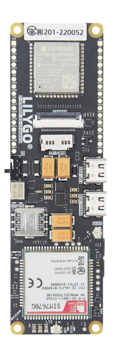
The ESP32 LilyGO is a versatile development board manufactured by ESP32, featuring the powerful ESP32 microcontroller. Known for its integrated Wi-Fi and Bluetooth capabilities, this board is ideal for Internet of Things (IoT) applications. It provides a variety of interfaces, including GPIO, ADC, and PWM, enabling developers to create projects ranging from smart home devices to industrial automation systems.
Explore Projects Built with esp32lilygo

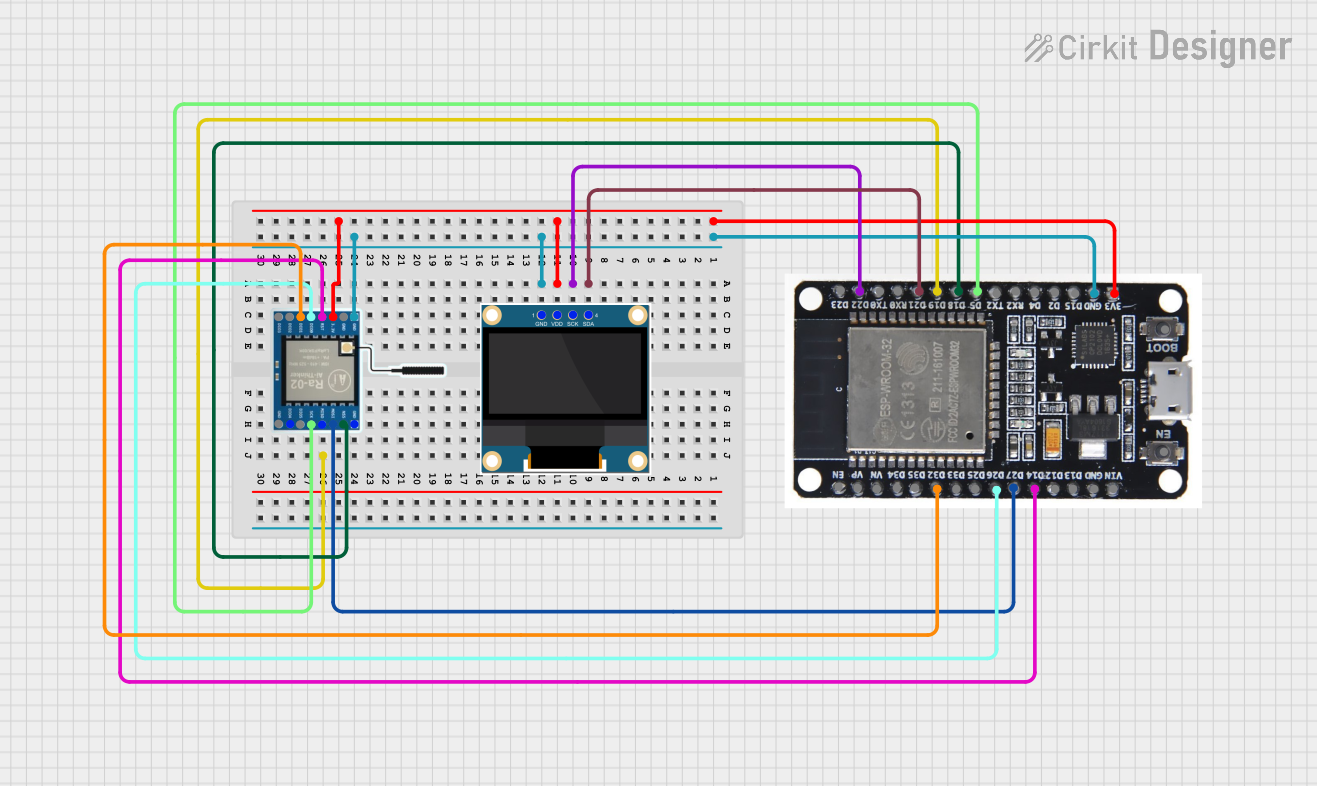
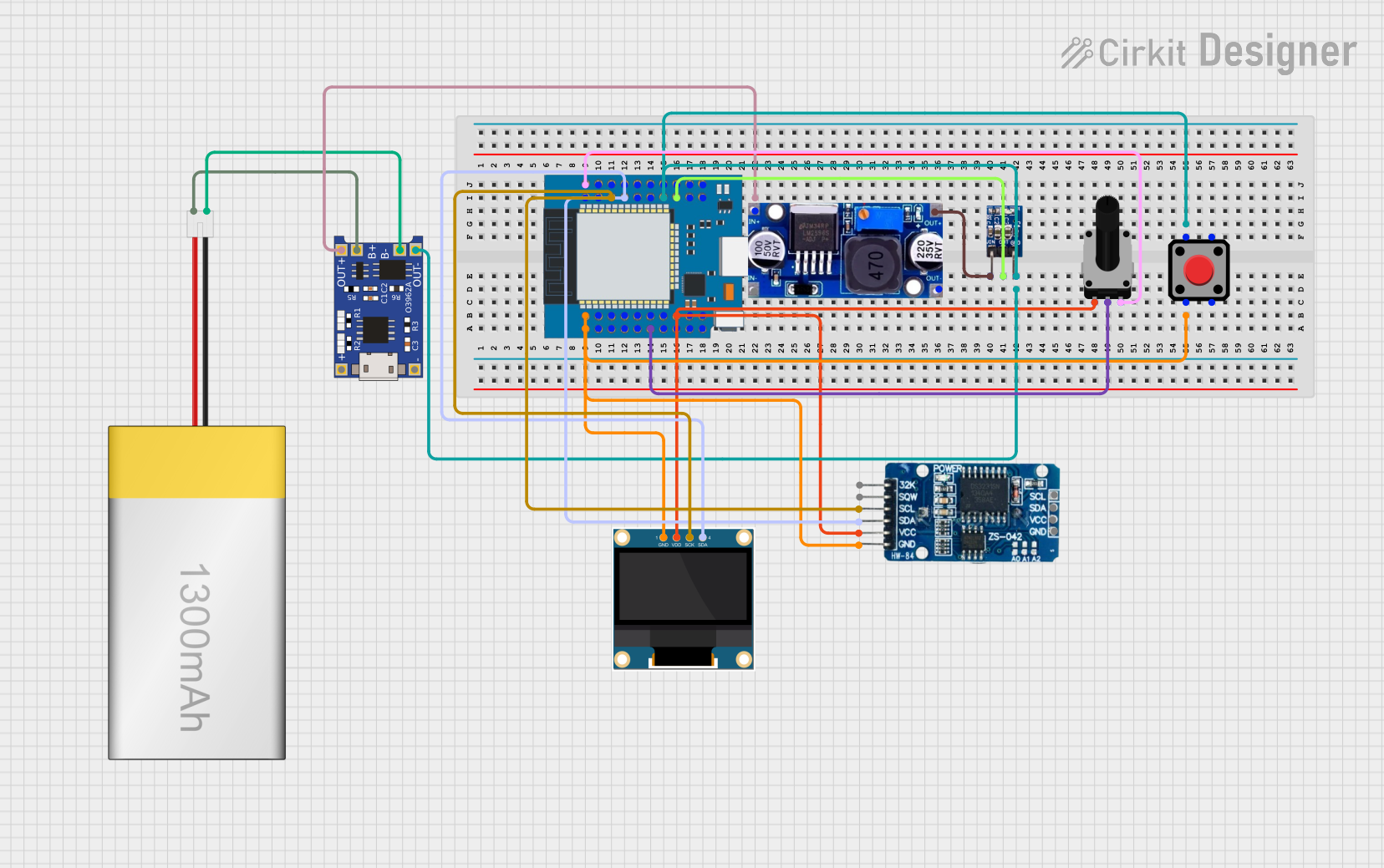

Explore Projects Built with esp32lilygo
Common Applications and Use Cases
- IoT Devices: Smart home automation, environmental monitoring, and connected appliances.
- Wearable Technology: Fitness trackers and health monitoring devices.
- Robotics: Motor control and sensor integration.
- Prototyping: Rapid development of wireless communication systems.
- Educational Projects: Learning embedded systems and wireless communication.
Technical Specifications
The ESP32 LilyGO is built around the ESP32 microcontroller, offering robust performance and connectivity. Below are the key technical details:
Key Specifications
| Parameter | Value |
|---|---|
| Microcontroller | ESP32 Dual-Core Xtensa LX6 |
| Clock Speed | Up to 240 MHz |
| Flash Memory | 4 MB (varies by model) |
| SRAM | 520 KB |
| Wi-Fi | 802.11 b/g/n (2.4 GHz) |
| Bluetooth | v4.2 BR/EDR and BLE |
| Operating Voltage | 3.3V |
| Input Voltage Range | 5V (via USB) |
| GPIO Pins | 34 (varies by model) |
| ADC Channels | Up to 18 |
| PWM Channels | 16 |
| Communication Interfaces | UART, SPI, I2C, I2S, CAN |
| Power Consumption | Ultra-low power modes available |
Pin Configuration and Descriptions
The ESP32 LilyGO features a variety of pins for different functionalities. Below is a general pinout description:
| Pin Name | Functionality | Description |
|---|---|---|
| GPIO0 | General Purpose I/O, Boot Mode | Used for boot mode selection during startup. |
| GPIO2 | General Purpose I/O, ADC, PWM | Can be used for analog input or PWM output. |
| GPIO4 | General Purpose I/O, ADC, PWM | Supports analog input and PWM functionality. |
| GPIO5 | General Purpose I/O, ADC, PWM | Commonly used for digital or analog signals. |
| GPIO12 | General Purpose I/O, ADC, PWM | Configurable for multiple purposes. |
| GPIO13 | General Purpose I/O, ADC, PWM | Often used for LED control or sensors. |
| GPIO14 | General Purpose I/O, ADC, PWM | Suitable for motor control or other outputs. |
| GPIO15 | General Purpose I/O, ADC, PWM | Can be used for digital or analog signals. |
| 3V3 | Power Supply | Provides 3.3V output for external components. |
| GND | Ground | Common ground for the circuit. |
Note: The exact pinout may vary depending on the specific LilyGO model. Refer to the datasheet for your board.
Usage Instructions
How to Use the ESP32 LilyGO in a Circuit
Powering the Board:
- Connect the board to your computer or power source via the USB port (5V input).
- Alternatively, use the 3.3V pin for external power supply.
Programming the Board:
- Install the Arduino IDE or PlatformIO for development.
- Add the ESP32 board manager URL to the Arduino IDE:
https://dl.espressif.com/dl/package_esp32_index.json - Select the appropriate ESP32 board under Tools > Board.
Connecting Peripherals:
- Use GPIO pins for digital or analog input/output.
- Connect sensors, actuators, or other devices to the appropriate pins.
- Ensure proper voltage levels to avoid damage.
Uploading Code:
- Write your code in the Arduino IDE or another supported environment.
- Connect the board via USB and select the correct COM port.
- Click Upload to flash the code onto the ESP32 LilyGO.
Example Code: Blinking an LED
Here is a simple example to blink an LED connected to GPIO2:
// Define the GPIO pin for the LED
#define LED_PIN 2

void setup() {
  pinMode(LED_PIN, OUTPUT); // Set GPIO2 as an output pin
}

void loop() {
  digitalWrite(LED_PIN, HIGH); // Turn the LED on
  delay(1000);                 // Wait for 1 second
  digitalWrite(LED_PIN, LOW);  // Turn the LED off
  delay(1000);                 // Wait for 1 second
}
Important Considerations and Best Practices
- Voltage Levels: Ensure all connected peripherals operate at 3.3V logic levels. Use level shifters if necessary.
- Power Supply: Avoid exceeding the input voltage range to prevent damage.
- Wi-Fi and Bluetooth: Keep the antenna area clear of obstructions for optimal signal strength.
- Deep Sleep Mode: Use deep sleep to reduce power consumption in battery-powered applications.
Troubleshooting and FAQs
Common Issues and Solutions
Board Not Detected by Computer:
- Ensure the USB cable is functional and supports data transfer.
- Install the correct USB-to-serial driver for the ESP32.
Code Upload Fails:
- Check the selected board and COM port in the Arduino IDE.
- Press and hold the BOOT button while uploading the code.
Wi-Fi Connection Issues:
- Verify the SSID and password in your code.
- Ensure the router operates on the 2.4 GHz band (ESP32 does not support 5 GHz).
Random Resets or Instability:
- Check the power supply for sufficient current (at least 500 mA).
- Avoid using GPIO pins that are reserved for boot mode during startup.
FAQs
Q: Can I use the ESP32 LilyGO with a battery?
A: Yes, the board supports battery operation. Use the onboard battery connector (if available) or connect a 3.7V LiPo battery to the appropriate pins.
Q: How do I enable deep sleep mode?
A: Use the esp_deep_sleep_start() function in your code. Refer to the ESP32 documentation for detailed instructions.
Q: Can I use the ESP32 LilyGO for audio applications?
A: Yes, the ESP32 supports I2S for audio input/output. You can connect external DACs or microphones for audio processing.
Q: Is the ESP32 LilyGO compatible with Arduino libraries?
A: Most Arduino libraries are compatible with the ESP32. However, some may require modifications for specific hardware features.
By following this documentation, you can effectively utilize the ESP32 LilyGO for a wide range of projects and applications.