How to Use SPEEDYBEE F405 WING Wires Board Back: Examples, Pinouts, and Specs
Introduction
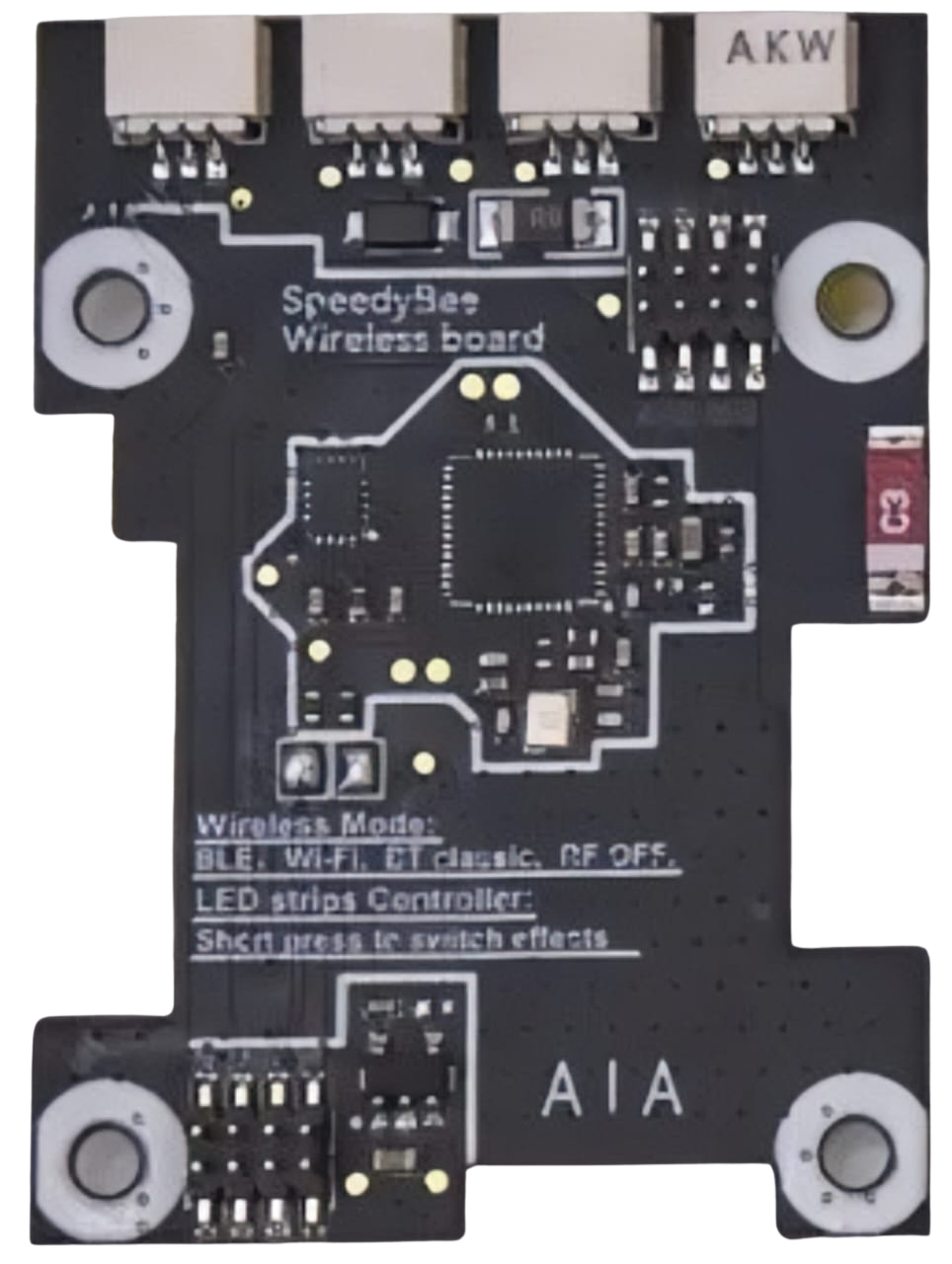
The SPEEDYBEE F405 WING is a versatile flight controller designed for fixed-wing and VTOL (Vertical Take-Off and Landing) drones. It is equipped with advanced features such as an F4 processor, multiple UARTs, and integrated Bluetooth for wireless configuration. This board is ideal for hobbyists and professionals looking to build high-performance drones with reliable and efficient control systems.
Explore Projects Built with SPEEDYBEE F405 WING Wires Board Back


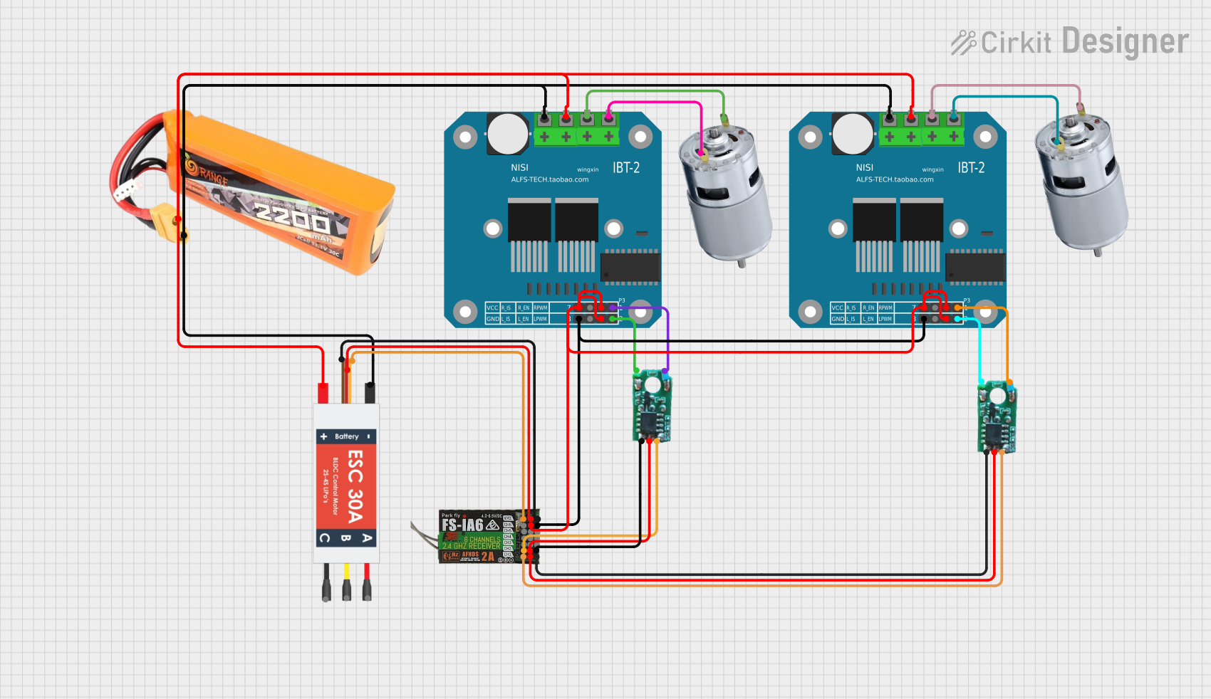

Explore Projects Built with SPEEDYBEE F405 WING Wires Board Back
Common Applications and Use Cases
- Fixed-wing drones for aerial photography and mapping
- VTOL drones for industrial and commercial applications
- FPV (First-Person View) drones for racing and freestyle flying
- Educational projects and research in UAV (Unmanned Aerial Vehicle) development
Technical Specifications
Key Technical Details
- Processor: STM32F405RGT6 (F4 series, 32-bit ARM Cortex-M4)
- Input Voltage: 7V–36V (2S–8S LiPo battery)
- BEC Output: 5V/2A and 9V/2A
- IMU (Inertial Measurement Unit): MPU6000 (6-axis gyro and accelerometer)
- UART Ports: 6 UARTs for peripherals (e.g., GPS, telemetry, receiver)
- Wireless Configuration: Integrated Bluetooth for SpeedyBee app
- Flash Memory: 16MB for Blackbox logging
- PWM Outputs: 8 PWM channels for servos and ESCs
- Dimensions: 36mm x 36mm (standard 30.5mm x 30.5mm mounting holes)
- Weight: 7.5g
Pin Configuration and Descriptions
The SPEEDYBEE F405 WING features a variety of pins for connecting peripherals. Below is the pinout description:
| Pin Name | Function | Description |
|---|---|---|
| GND | Ground | Connect to the ground of the power source or peripherals. |
| VBAT | Battery Voltage Input | Connect to the positive terminal of the LiPo battery (7V–36V). |
| 5V | 5V Output | Provides 5V power for peripherals (max 2A). |
| 9V | 9V Output | Provides 9V power for peripherals (max 2A). |
| UART1 (TX/RX) | UART1 Serial Communication | For connecting GPS, telemetry, or other serial devices. |
| UART2 (TX/RX) | UART2 Serial Communication | Additional UART for peripherals. |
| PWM1–PWM8 | PWM Outputs | For connecting ESCs or servos (supports up to 8 channels). |
| SCL/SDA | I2C Communication | For connecting I2C devices like airspeed sensors. |
| BOOT | Bootloader Mode | Used for firmware flashing or recovery. |
| LED | Status LED Output | Connect to an external LED for status indication. |
Usage Instructions
How to Use the Component in a Circuit
Powering the Board:
- Connect the VBAT pin to the positive terminal of a 2S–8S LiPo battery.
- Ensure the GND pin is connected to the battery's ground terminal.
- Optionally, use the 5V or 9V output pins to power external peripherals.
Connecting Peripherals:
- Use the UART pins to connect devices like GPS modules, telemetry radios, or receivers.
- Connect ESCs or servos to the PWM output pins (PWM1–PWM8).
- For I2C devices, connect the SCL and SDA pins to the corresponding pins on the device.
Configuring the Board:
- Download the SpeedyBee app on your smartphone.
- Power the board and enable Bluetooth.
- Open the app, connect to the board, and configure settings such as flight modes, PID tuning, and failsafe options.
Flashing Firmware:
- Hold the BOOT pin while powering the board to enter bootloader mode.
- Use Betaflight Configurator or INAV Configurator to flash the desired firmware.
Important Considerations and Best Practices
- Voltage Compatibility: Ensure the input voltage does not exceed the specified range (7V–36V).
- Heat Management: Avoid overheating by ensuring proper airflow around the board.
- Secure Connections: Use quality connectors and solder joints to prevent disconnections during flight.
- Firmware Updates: Regularly update the firmware to access new features and bug fixes.
- Blackbox Logging: Use the onboard 16MB flash memory to log flight data for analysis and troubleshooting.
Example Code for Arduino UNO Integration
Although the SPEEDYBEE F405 WING is primarily used in drones, it can communicate with an Arduino UNO via UART. Below is an example code snippet for reading data from the board:
#include <SoftwareSerial.h>

// Define RX and TX pins for SoftwareSerial
SoftwareSerial speedyBeeSerial(10, 11); // RX = pin 10, TX = pin 11

void setup() {
  // Initialize serial communication
  Serial.begin(9600); // For debugging via Serial Monitor
  speedyBeeSerial.begin(115200); // Communication with SPEEDYBEE F405 WING

  Serial.println("Starting communication with SPEEDYBEE F405 WING...");
}

void loop() {
  // Check if data is available from the SPEEDYBEE F405 WING
  if (speedyBeeSerial.available()) {
    String data = speedyBeeSerial.readString(); // Read incoming data
    Serial.println("Data from SPEEDYBEE: " + data); // Print data to Serial Monitor
  }

  // Send a test command to the SPEEDYBEE F405 WING
  speedyBeeSerial.println("Test Command");
  delay(1000); // Wait for 1 second before sending the next command
}
Troubleshooting and FAQs
Common Issues Users Might Face
Board Not Powering On:
- Cause: Incorrect wiring or insufficient input voltage.
- Solution: Verify the VBAT and GND connections and ensure the battery voltage is within the 7V–36V range.
Bluetooth Not Connecting:
- Cause: Bluetooth is disabled or interference from other devices.
- Solution: Ensure the board is powered on and within range. Restart the SpeedyBee app and try reconnecting.
ESCs or Servos Not Responding:
- Cause: Incorrect PWM configuration or wiring.
- Solution: Check the PWM output settings in the SpeedyBee app or Betaflight Configurator. Verify the connections to the ESCs or servos.
Firmware Flashing Fails:
- Cause: Incorrect bootloader mode or USB driver issues.
- Solution: Hold the BOOT pin while powering the board. Ensure the correct USB drivers are installed on your computer.
Solutions and Tips for Troubleshooting
- Use a multimeter to check voltage levels at the VBAT and 5V/9V pins.
- Refer to the official SpeedyBee documentation for detailed configuration guides.
- If the board becomes unresponsive, try reflashing the firmware in bootloader mode.
- For advanced debugging, use the Blackbox logs to analyze flight data and identify issues.