How to Use Relay_switch: Examples, Pinouts, and Specs
Introduction
The MXRS CYT1073 Relay Switch is an electromechanical device designed to control high-power circuits using low-power signals. It operates by utilizing an electromagnetic coil to mechanically open or close electrical contacts, enabling seamless switching between circuits. This component is widely used in applications where electrical isolation, high-current control, or automation is required.
Explore Projects Built with Relay_switch


Explore Projects Built with Relay_switch
Common Applications and Use Cases
- Home Automation: Controlling lights, fans, and appliances remotely.
- Industrial Automation: Switching high-power motors or machinery.
- Microcontroller Projects: Interfacing with Arduino, Raspberry Pi, or other microcontrollers.
- Power Management: Isolating and controlling high-voltage circuits safely.
- Automotive Systems: Controlling headlights, horns, or other vehicle electronics.
Technical Specifications
The following table outlines the key technical details of the MXRS CYT1073 Relay Switch:
| Parameter | Value |
|---|---|
| Manufacturer | MXRS |
| Part ID | CYT1073 |
| Coil Voltage | 5V DC |
| Operating Voltage Range | 4.5V to 5.5V DC |
| Contact Rating | 10A at 250V AC / 10A at 30V DC |
| Coil Resistance | 70Ω |
| Switching Time | 10ms (Operate), 5ms (Release) |
| Insulation Resistance | ≥100MΩ at 500V DC |
| Dielectric Strength | 1500V AC (1 minute) |
| Mechanical Life | 10 million operations |
| Electrical Life | 100,000 operations |
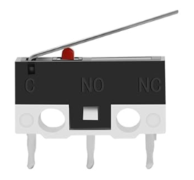
Pin Configuration and Descriptions
The MXRS CYT1073 Relay Switch has a standard 5-pin configuration. The table below describes each pin:
| Pin Number | Name | Description |
|---|---|---|
| 1 | Coil (+) | Positive terminal of the electromagnetic coil. |
| 2 | Coil (-) | Negative terminal of the electromagnetic coil. |
| 3 | Common (COM) | Common terminal for the relay switch. |
| 4 | Normally Open (NO) | Open circuit when the relay is inactive; closes when the relay is activated. |
| 5 | Normally Closed (NC) | Closed circuit when the relay is inactive; opens when the relay is activated. |
Usage Instructions
How to Use the Relay Switch in a Circuit
- Power the Coil: Connect the coil terminals (Pin 1 and Pin 2) to a 5V DC power source. Ensure the current supplied matches the coil's requirements.
- Control the Load: Connect the high-power circuit to the Common (COM) terminal (Pin 3) and either the Normally Open (NO) or Normally Closed (NC) terminal (Pin 4 or Pin 5), depending on the desired behavior:
- Use the NO terminal if the circuit should be off by default and activated when the relay is energized.
- Use the NC terminal if the circuit should be on by default and deactivated when the relay is energized.
- Isolation: Ensure proper electrical isolation between the low-power control circuit and the high-power load circuit to prevent damage or hazards.
Important Considerations and Best Practices
- Diode Protection: Always connect a flyback diode across the coil terminals to protect the circuit from voltage spikes caused by the relay's inductive load.
- Current Ratings: Ensure the load current does not exceed the relay's contact rating (10A).
- Heat Dissipation: Avoid overheating by providing adequate ventilation or heat sinks if the relay operates continuously.
- Microcontroller Interfacing: Use a transistor or relay driver module to interface the relay with microcontrollers like Arduino, as they cannot directly supply the required current.
Example: Connecting the Relay to an Arduino UNO
Below is an example of how to control the MXRS CYT1073 Relay Switch using an Arduino UNO:
Circuit Connections
- Connect the relay's Coil (+) to a digital pin on the Arduino (e.g., Pin 7) through a transistor.
- Connect the relay's Coil (-) to the Arduino's GND.
- Connect the load circuit to the COM and NO terminals of the relay.
Arduino Code
// Define the relay pin
const int relayPin = 7;

void setup() {
  // Set the relay pin as an output
  pinMode(relayPin, OUTPUT);

  // Ensure the relay is off at startup
  digitalWrite(relayPin, LOW);
}

void loop() {
  // Turn the relay on
  digitalWrite(relayPin, HIGH);
  delay(1000); // Keep the relay on for 1 second

  // Turn the relay off
  digitalWrite(relayPin, LOW);
  delay(1000); // Keep the relay off for 1 second
}
Troubleshooting and FAQs
Common Issues and Solutions
Relay Not Activating
- Cause: Insufficient voltage or current to the coil.
- Solution: Verify the power supply voltage (4.5V to 5.5V DC) and ensure it meets the coil's current requirements.
Load Not Switching
- Cause: Incorrect wiring of the load circuit.
- Solution: Double-check the connections to the COM, NO, and NC terminals.
Voltage Spikes Damaging Components
- Cause: Lack of a flyback diode across the coil.
- Solution: Install a diode (e.g., 1N4007) across the coil terminals, with the cathode connected to the Coil (+).
Relay Overheating
- Cause: Exceeding the relay's current rating or continuous operation.
- Solution: Reduce the load current or provide proper cooling.
FAQs
Q: Can I use the relay with a 3.3V microcontroller?
A: Yes, but you will need a transistor or relay driver circuit to step up the voltage to 5V for the coil.Q: What type of diode should I use for flyback protection?
A: A general-purpose diode like the 1N4007 is suitable for this purpose.Q: Can the relay switch both AC and DC loads?
A: Yes, the relay can handle up to 250V AC or 30V DC, as long as the current does not exceed 10A.Q: How do I know if the relay is working?
A: You should hear a clicking sound when the relay switches. Additionally, you can measure continuity between the COM and NO/NC terminals to verify the switching behavior.