How to Use RTC DS13072: Examples, Pinouts, and Specs
Introduction
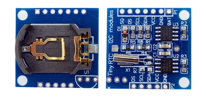
The RTC DS13072 is a high-precision, low-power real-time clock and calendar chip designed by Electronics Hut. It is engineered to maintain accurate time and date information, functioning even when the primary device power is off. This component is ideal for applications such as embedded systems, data loggers, clocks, and smart devices where timekeeping is crucial.
Explore Projects Built with RTC DS13072

Explore Projects Built with RTC DS13072
Common Applications and Use Cases
- Embedded systems requiring time stamps
- Data logging with time information
- Digital clocks and watches
- Smart home devices for scheduling and timers
- IoT devices for timestamping sensor data
Technical Specifications
Key Technical Details
- Timekeeping Accuracy: ±2ppm from 0°C to +40°C
- Battery Backup Current: 1µA (typical)
- Operating Voltage: 2.0V to 5.5V
- Interface: I2C and SPI
- Operating Temperature Range: -40°C to +85°C
- Package: 8-pin DIP or SOIC
Pin Configuration and Descriptions
| Pin Number | Name | Description |
|---|---|---|
| 1 | VCC | Power supply pin (2.0V to 5.5V) |
| 2 | GND | Ground pin |
| 3 | SDA | Serial Data for I2C interface |
| 4 | SCL | Serial Clock for I2C interface |
| 5 | MOSI | Master Out Slave In for SPI interface |
| 6 | MISO | Master In Slave Out for SPI interface |
| 7 | SCLK | Serial Clock for SPI interface |
| 8 | /CS | Chip Select for SPI interface |
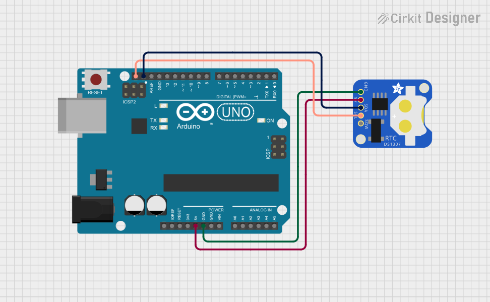
Usage Instructions
How to Use the Component in a Circuit
- Power Supply: Connect VCC to a 2.0V to 5.5V power source and GND to the system ground.
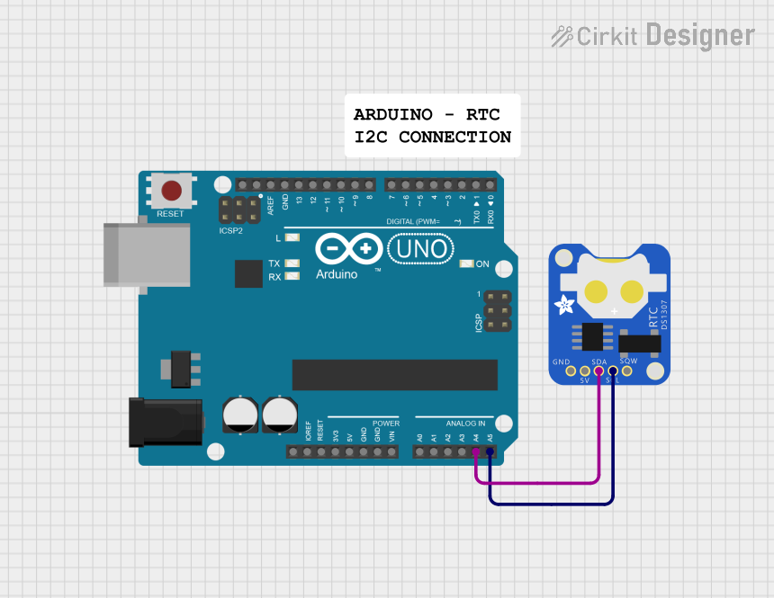
- Interface Selection: Choose between I2C or SPI for communication with the microcontroller.
- Battery Backup: Attach a coin cell battery to the VCC and GND pins to enable timekeeping during power loss.
Important Considerations and Best Practices
- Ensure that the power supply is within the specified voltage range to prevent damage.
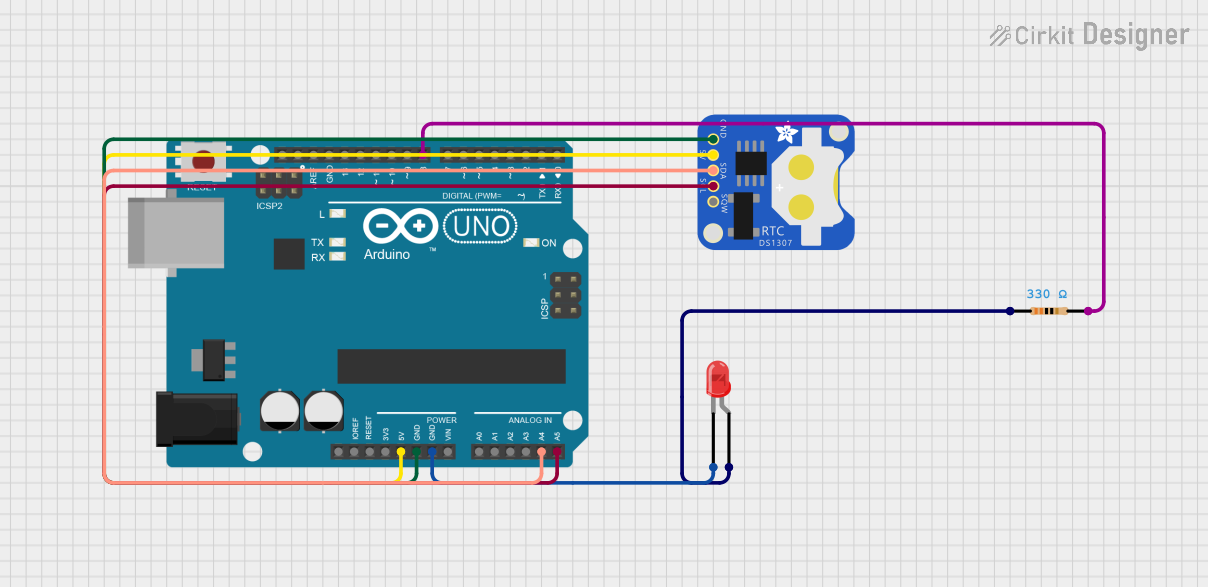
- Use pull-up resistors on the SDA and SCL lines when using the I2C interface.
- For SPI communication, ensure that the /CS pin is driven low to enable the device.
- Place a decoupling capacitor close to the VCC pin to filter out noise.
- Keep the traces between the microcontroller and the RTC as short as possible to reduce signal degradation.
Example Code for Arduino UNO
#include <Wire.h> // Include Wire library for I2C communication

// RTC DS13072 I2C address
#define DS13072_I2C_ADDRESS 0x68

void setup() {
  Wire.begin(); // Initialize I2C communication
  Serial.begin(9600); // Start serial communication at 9600 baud rate
  // Set initial time and date here if needed
}

void loop() {
  Wire.beginTransmission(DS13072_I2C_ADDRESS); // Start I2C transmission
  Wire.write(0); // Set DS13072 register pointer to 00h
  Wire.endTransmission();

  Wire.requestFrom(DS13072_I2C_ADDRESS, 7); // Request 7 bytes of data

  // Read data from the RTC and print it
  if (Wire.available() == 7) {
    // Convert the byte data to num
    int second = bcdToDec(Wire.read() & 0x7F);
    int minute = bcdToDec(Wire.read());
    int hour = bcdToDec(Wire.read() & 0x3F);
    int dayOfWeek = bcdToDec(Wire.read());
    int dayOfMonth = bcdToDec(Wire.read());
    int month = bcdToDec(Wire.read());
    int year = bcdToDec(Wire.read());

    // Print the date and time
    Serial.print(year);
    Serial.print("/");
    Serial.print(month);
    Serial.print("/");
    Serial.print(dayOfMonth);
    Serial.print(" ");
    Serial.print(hour);
    Serial.print(":");
    Serial.print(minute);
    Serial.print(":");
    Serial.println(second);
  }

  delay(1000); // Wait for a second
}

// Convert binary coded decimal to normal decimal numbers
int bcdToDec(byte val) {
  return (int)((val / 16 * 10) + (val % 16));
}
Troubleshooting and FAQs
Common Issues Users Might Face
- Incorrect Time: Ensure the initial time is set correctly and the battery backup is functioning.
- Communication Failure: Check the wiring, pull-up resistors on I2C lines, and /CS pin state for SPI.
- No Power: Verify the power supply voltage and connections.
Solutions and Tips for Troubleshooting
- Double-check the connections and solder joints for any loose or cold solder points.
- Use a multimeter to verify the voltage levels at the VCC and GND pins.
- Ensure that the microcontroller's I2C or SPI libraries are correctly initialized.
- Replace the battery if the RTC fails to keep time after power cycling.
FAQs
Q: Can the RTC DS13072 be used with both 3.3V and 5V systems? A: Yes, the RTC DS13072 operates within a range of 2.0V to 5.5V, making it compatible with both 3.3V and 5V systems.
Q: How long can the RTC keep time with a battery backup? A: The battery life depends on the quality and capacity of the coin cell used. With a typical 3V coin cell and the low backup current of the DS13072, it can last for several years.
Q: Is it necessary to use an external crystal with the DS13072? A: The DS13072 typically has an integrated crystal. However, check the specific module from Electronics Hut to confirm if an external crystal is needed or already included.