Cirkit Designer Logo
Cirkit Designer
Your all-in-one circuit design IDE
Home / 
Component Documentation

How to Use RS485 photo ISOLATE ADUM5402: Examples, Pinouts, and Specs

Image of RS485 photo ISOLATE ADUM5402
Cirkit Designer LogoDesign with RS485 photo ISOLATE ADUM5402 in Cirkit Designer

Introduction

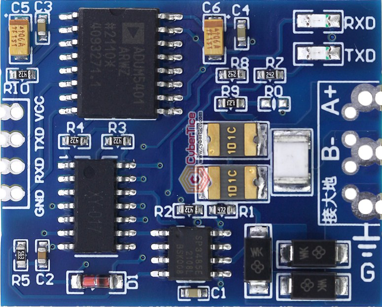
The RS485 Photo Isolate ADUM5402 is a high-performance, dual-channel digital isolator with integrated DC-DC power conversion. It is designed to provide electrical isolation and signal integrity in RS485 communication systems. The ADUM5402 uses Analog Devices' iCoupler® technology to achieve robust isolation while maintaining high data rates and low power consumption. Its integrated power isolation eliminates the need for external isolated power supplies, simplifying circuit design.

Explore Projects Built with RS485 photo ISOLATE ADUM5402

Use Cirkit Designer to design, explore, and prototype these projects online. Some projects support real-time simulation. Click "Open Project" to start designing instantly!
ESP32-Based Industrial Control System with RS485 Communication and I2C Interface
Image of DRIVER TESTER : A project utilizing RS485 photo ISOLATE ADUM5402 in a practical application
This circuit integrates a microcontroller with a display, digital potentiometer, IO expander, and opto-isolator board for signal interfacing and isolation. It includes a UART to RS485 converter for serial communication and a power converter to step down voltage for the system. The circuit is designed for control and communication in an isolated and protected environment.
Cirkit Designer LogoOpen Project in Cirkit Designer
STM32 and Arduino UNO Based Dual RS485 Communication Interface
Image of STM to Arduino RS485: A project utilizing RS485 photo ISOLATE ADUM5402 in a practical application
This circuit consists of two microcontrollers, an STM32F103C8T6 and an Arduino UNO, each interfaced with separate RS485 transceiver modules for serial communication. The STM32F103C8T6 controls the RE (Receiver Enable) and DE (Driver Enable) pins of one RS485 module to manage its operation, and communicates via the A9 and A10 pins for DI (Data Input) and RO (Receiver Output), respectively. The Arduino UNO is similarly connected to another RS485 module, with digital pins D2 and D3 interfacing with DI and RO, and D8 controlling both RE and DE. The RS485 modules are connected to each other through their A and B differential communication lines, enabling serial data exchange between the two microcontrollers over a robust and long-distance capable RS485 network.
Cirkit Designer LogoOpen Project in Cirkit Designer
ESP32-Based Wi-Fi Controlled 24V Input/Output Interface Module
Image of ESP32 4 på rad: A project utilizing RS485 photo ISOLATE ADUM5402 in a practical application
This circuit uses an ESP32 microcontroller to interface with a 3.3V PNP to 24V NPN photoelectric isolation module, which in turn connects to a 40-pin connector for general-purpose input and output. The 24V power supply provides the necessary voltage for the isolation module and the 40-pin connector, enabling the ESP32 to control and monitor high-voltage signals safely.
Cirkit Designer LogoOpen Project in Cirkit Designer
Arduino UNO Based RS-485 Communication System with Pushbutton Activation and LED Indicator
Image of tp: A project utilizing RS485 photo ISOLATE ADUM5402 in a practical application
This circuit consists of two Arduino UNO microcontrollers interfaced with RS-485 modules to enable serial communication over a differential bus, allowing for robust long-distance data transmission. One Arduino is configured as a master, sending a message when a pushbutton is pressed, while the other Arduino is set up as a slave, responding by lighting up an LED when the correct message is received. The system is powered by two separate 9V batteries, and a resistor is used to limit the current through the LED.
Cirkit Designer LogoOpen Project in Cirkit Designer

Explore Projects Built with RS485 photo ISOLATE ADUM5402

Use Cirkit Designer to design, explore, and prototype these projects online. Some projects support real-time simulation. Click "Open Project" to start designing instantly!
Image of DRIVER TESTER : A project utilizing RS485 photo ISOLATE ADUM5402 in a practical application
ESP32-Based Industrial Control System with RS485 Communication and I2C Interface
This circuit integrates a microcontroller with a display, digital potentiometer, IO expander, and opto-isolator board for signal interfacing and isolation. It includes a UART to RS485 converter for serial communication and a power converter to step down voltage for the system. The circuit is designed for control and communication in an isolated and protected environment.
Cirkit Designer LogoOpen Project in Cirkit Designer
Image of STM to Arduino RS485: A project utilizing RS485 photo ISOLATE ADUM5402 in a practical application
STM32 and Arduino UNO Based Dual RS485 Communication Interface
This circuit consists of two microcontrollers, an STM32F103C8T6 and an Arduino UNO, each interfaced with separate RS485 transceiver modules for serial communication. The STM32F103C8T6 controls the RE (Receiver Enable) and DE (Driver Enable) pins of one RS485 module to manage its operation, and communicates via the A9 and A10 pins for DI (Data Input) and RO (Receiver Output), respectively. The Arduino UNO is similarly connected to another RS485 module, with digital pins D2 and D3 interfacing with DI and RO, and D8 controlling both RE and DE. The RS485 modules are connected to each other through their A and B differential communication lines, enabling serial data exchange between the two microcontrollers over a robust and long-distance capable RS485 network.
Cirkit Designer LogoOpen Project in Cirkit Designer
Image of ESP32 4 på rad: A project utilizing RS485 photo ISOLATE ADUM5402 in a practical application
ESP32-Based Wi-Fi Controlled 24V Input/Output Interface Module
This circuit uses an ESP32 microcontroller to interface with a 3.3V PNP to 24V NPN photoelectric isolation module, which in turn connects to a 40-pin connector for general-purpose input and output. The 24V power supply provides the necessary voltage for the isolation module and the 40-pin connector, enabling the ESP32 to control and monitor high-voltage signals safely.
Cirkit Designer LogoOpen Project in Cirkit Designer
Image of tp: A project utilizing RS485 photo ISOLATE ADUM5402 in a practical application
Arduino UNO Based RS-485 Communication System with Pushbutton Activation and LED Indicator
This circuit consists of two Arduino UNO microcontrollers interfaced with RS-485 modules to enable serial communication over a differential bus, allowing for robust long-distance data transmission. One Arduino is configured as a master, sending a message when a pushbutton is pressed, while the other Arduino is set up as a slave, responding by lighting up an LED when the correct message is received. The system is powered by two separate 9V batteries, and a resistor is used to limit the current through the LED.
Cirkit Designer LogoOpen Project in Cirkit Designer

Common Applications and Use Cases

  • Industrial automation and control systems
  • RS485/RS422 communication networks
  • Motor control and drives
  • Data acquisition systems
  • Medical equipment requiring isolation
  • High-noise environments where signal integrity is critical

Technical Specifications

Key Technical Details

Parameter Value
Isolation Voltage 2.5 kV RMS
Data Rate Up to 25 Mbps
Supply Voltage (VDD1/VDD2) 3.0 V to 5.5 V
Output Power Up to 500 mW
Quiescent Current 10 mA (typical)
Operating Temperature -40°C to +105°C
Package Type 16-lead SOIC-W

Pin Configuration and Descriptions

Pin Number Name Description
1 VDD1 Primary-side power supply input
2 GND1 Primary-side ground
3 VISO Isolated power output
4 GNDISO Isolated ground
5 VDD2 Secondary-side power supply input
6 GND2 Secondary-side ground
7 TXD Transmit data input
8 RXD Receive data output
9-16 NC No connection (reserved for future use)

Usage Instructions

How to Use the Component in a Circuit

  1. Power Supply Connections:

    • Connect a 3.0 V to 5.5 V power supply to VDD1 and GND1 for the primary side.
    • The integrated DC-DC converter will generate isolated power at VISO and GNDISO.
    • Use VISO and GNDISO to power the secondary side of the circuit.
  2. Signal Connections:

    • Connect the RS485 driver or microcontroller's TX pin to the TXD pin of the ADUM5402.
    • Connect the RXD pin to the RX pin of the RS485 driver or microcontroller.
    • Ensure proper termination resistors are used in the RS485 network to maintain signal integrity.
  3. Isolation:

    • The ADUM5402 provides galvanic isolation between the primary and secondary sides.
    • Ensure that the ground planes of the primary and secondary sides are not directly connected.
  4. Bypass Capacitors:

    • Place decoupling capacitors (e.g., 0.1 µF and 10 µF) close to the VDD1 and VISO pins to reduce noise and improve stability.

Important Considerations and Best Practices

  • Thermal Management: The ADUM5402 can generate heat during operation. Ensure adequate ventilation or heat sinking if operating at high power levels.
  • Signal Integrity: Use twisted-pair cables for RS485 communication to minimize noise and crosstalk.
  • PCB Layout: Maintain sufficient creepage and clearance distances between the primary and secondary sides to ensure proper isolation.
  • ESD Protection: Add TVS diodes or other ESD protection devices to the RS485 lines for enhanced robustness.

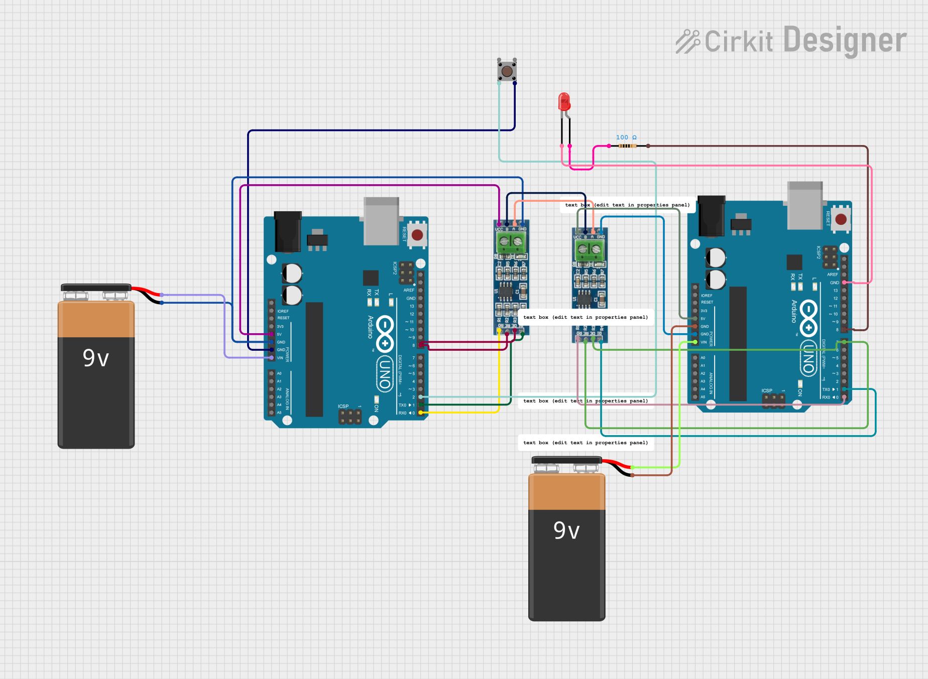
Example: Connecting to an Arduino UNO

The ADUM5402 can be used to isolate an Arduino UNO from an RS485 network. Below is an example code snippet for sending and receiving data over RS485 using the ADUM5402.

#include <SoftwareSerial.h>

// Define RS485 communication pins
#define RS485_TX 10  // Arduino pin connected to ADUM5402 TXD
#define RS485_RX 11  // Arduino pin connected to ADUM5402 RXD

// Initialize SoftwareSerial for RS485 communication
SoftwareSerial RS485Serial(RS485_RX, RS485_TX);

void setup() {
  // Start serial communication for debugging
  Serial.begin(9600);
  Serial.println("RS485 Communication Initialized");

  // Start RS485 communication
  RS485Serial.begin(9600);
}

void loop() {
  // Send data over RS485
  RS485Serial.println("Hello, RS485!");
  Serial.println("Data sent: Hello, RS485!");

  // Wait for a response
  if (RS485Serial.available()) {
    String receivedData = RS485Serial.readString();
    Serial.print("Data received: ");
    Serial.println(receivedData);
  }

  delay(1000); // Wait 1 second before sending the next message
}

Troubleshooting and FAQs

Common Issues and Solutions

  1. No Power on the Secondary Side:

    • Ensure that VDD1 is within the specified range (3.0 V to 5.5 V).
    • Check for proper connections to VDD1 and GND1.
    • Verify that bypass capacitors are installed correctly.
  2. Data Transmission Errors:

    • Verify that the baud rate of the RS485 driver matches the Arduino or microcontroller.
    • Check for proper termination resistors in the RS485 network.
    • Ensure that the TXD and RXD pins are correctly connected.
  3. Excessive Heat Generation:

    • Confirm that the load on the isolated power output (VISO) does not exceed 500 mW.
    • Improve ventilation or add a heat sink if necessary.
  4. Noisy Signals:

    • Use shielded or twisted-pair cables for RS485 communication.
    • Add decoupling capacitors close to the power supply pins.

FAQs

Q: Can the ADUM5402 be used for other communication protocols?
A: Yes, the ADUM5402 can isolate other digital communication protocols, such as SPI or I2C, as long as the data rate and voltage levels are within its specifications.

Q: What is the maximum cable length for RS485 communication?
A: The maximum cable length depends on the data rate and cable type. For example, at 9600 bps, RS485 can typically support up to 1200 meters.

Q: Is the ADUM5402 suitable for medical applications?
A: Yes, the ADUM5402 provides robust isolation and is suitable for medical applications, but ensure compliance with relevant medical safety standards.