Cirkit Designer Logo
Cirkit Designer
Your all-in-one circuit design IDE
Home / 
Component Documentation

How to Use BNC Female Jack Terminal Block: Examples, Pinouts, and Specs

Image of BNC Female Jack Terminal Block
Cirkit Designer LogoDesign with BNC Female Jack Terminal Block in Cirkit Designer

Introduction

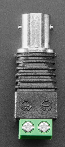
The BNC Female Jack Terminal Block (Adafruit Product ID: 2889) is a versatile connector designed for use with coaxial cables. It features a female BNC connector mounted on a terminal block, enabling quick and secure wiring without the need for soldering. This component is ideal for applications requiring reliable transmission of video or RF signals, such as in surveillance systems, test equipment, and communication devices.

Explore Projects Built with BNC Female Jack Terminal Block

Use Cirkit Designer to design, explore, and prototype these projects online. Some projects support real-time simulation. Click "Open Project" to start designing instantly!
Multi-Channel Load Cell Measurement System with JYS60 Amplifiers and DAQ Integration
Image of Load Cell Circuit: A project utilizing BNC Female Jack Terminal Block in a practical application
This is a multi-channel load cell measurement system with several JYS60 amplifiers connected to load cells for weight or force sensing. The amplified signals are directed to a DAQ system for data capture, and power is supplied through a barrel jack. Grounding is achieved via an AdaGator Side Black component.
Cirkit Designer LogoOpen Project in Cirkit Designer
Battery-Powered Multi-Voltage Supply with Barrel Jack Connectors
Image of Battery Setup: A project utilizing BNC Female Jack Terminal Block in a practical application
This circuit consists of multiple 9V batteries connected in series and parallel configurations to provide power to three separate 2.1mm barrel jacks. Each barrel jack receives a different combination of series and parallel battery connections to achieve the desired voltage and current levels.
Cirkit Designer LogoOpen Project in Cirkit Designer
Satellite Compass and Network-Integrated GPS Data Processing System
Image of GPS 시스템 측정 구성도_241016: A project utilizing BNC Female Jack Terminal Block in a practical application
This circuit comprises a satellite compass, a mini PC, two GPS antennas, power supplies, a network switch, media converters, and an atomic rubidium clock. The satellite compass is powered by a triple output DC power supply and interfaces with an RS232 splitter for 1PPS signals. The mini PCs are connected to the USRP B200 devices via USB for data and power, and to media converters via Ethernet, which in turn connect to a network switch using fiber optic links. The antennas are connected to the USRP B200s through RF directional couplers, and the atomic clock provides a 1PPS input to the RS232 splitter.
Cirkit Designer LogoOpen Project in Cirkit Designer
Audio Signal Conditioning Circuit with 3.5mm Jacks and Passive Components
Image of BA: A project utilizing BNC Female Jack Terminal Block in a practical application
This circuit appears to be an audio signal processing or filtering circuit, utilizing multiple 3.5mm jacks for input and output connections, resistors, and capacitors to form various RC (resistor-capacitor) networks. The configuration suggests it could be used for tasks such as audio signal conditioning, noise filtering, or impedance matching.
Cirkit Designer LogoOpen Project in Cirkit Designer

Explore Projects Built with BNC Female Jack Terminal Block

Use Cirkit Designer to design, explore, and prototype these projects online. Some projects support real-time simulation. Click "Open Project" to start designing instantly!
Image of Load Cell Circuit: A project utilizing BNC Female Jack Terminal Block in a practical application
Multi-Channel Load Cell Measurement System with JYS60 Amplifiers and DAQ Integration
This is a multi-channel load cell measurement system with several JYS60 amplifiers connected to load cells for weight or force sensing. The amplified signals are directed to a DAQ system for data capture, and power is supplied through a barrel jack. Grounding is achieved via an AdaGator Side Black component.
Cirkit Designer LogoOpen Project in Cirkit Designer
Image of Battery Setup: A project utilizing BNC Female Jack Terminal Block in a practical application
Battery-Powered Multi-Voltage Supply with Barrel Jack Connectors
This circuit consists of multiple 9V batteries connected in series and parallel configurations to provide power to three separate 2.1mm barrel jacks. Each barrel jack receives a different combination of series and parallel battery connections to achieve the desired voltage and current levels.
Cirkit Designer LogoOpen Project in Cirkit Designer
Image of GPS 시스템 측정 구성도_241016: A project utilizing BNC Female Jack Terminal Block in a practical application
Satellite Compass and Network-Integrated GPS Data Processing System
This circuit comprises a satellite compass, a mini PC, two GPS antennas, power supplies, a network switch, media converters, and an atomic rubidium clock. The satellite compass is powered by a triple output DC power supply and interfaces with an RS232 splitter for 1PPS signals. The mini PCs are connected to the USRP B200 devices via USB for data and power, and to media converters via Ethernet, which in turn connect to a network switch using fiber optic links. The antennas are connected to the USRP B200s through RF directional couplers, and the atomic clock provides a 1PPS input to the RS232 splitter.
Cirkit Designer LogoOpen Project in Cirkit Designer
Image of BA: A project utilizing BNC Female Jack Terminal Block in a practical application
Audio Signal Conditioning Circuit with 3.5mm Jacks and Passive Components
This circuit appears to be an audio signal processing or filtering circuit, utilizing multiple 3.5mm jacks for input and output connections, resistors, and capacitors to form various RC (resistor-capacitor) networks. The configuration suggests it could be used for tasks such as audio signal conditioning, noise filtering, or impedance matching.
Cirkit Designer LogoOpen Project in Cirkit Designer

Common Applications

  • Video Signal Transmission: Used in CCTV systems, video monitors, and broadcast equipment.
  • RF Signal Applications: Suitable for radio frequency signal connections in communication systems.
  • Test and Measurement: Commonly used in oscilloscopes, signal generators, and other lab equipment.
  • Prototyping and DIY Projects: Simplifies integration of BNC connections into custom circuits.

Technical Specifications

Key Technical Details

Parameter Specification
Manufacturer Adafruit
Manufacturer Part ID Product ID: 2889
Connector Type BNC Female Jack
Terminal Block Type Screw terminal block
Supported Cable Type Coaxial cables
Signal Compatibility Video signals, RF signals
Mounting Style Panel mount or free-standing
Dimensions 38mm x 18mm x 15mm (approx.)
Weight ~10g

Pin Configuration and Descriptions

The BNC Female Jack Terminal Block has two primary connections on the terminal block:

Terminal Block Pin Description
Signal Pin Connects to the center conductor of the coaxial cable (signal).
Ground Pin Connects to the outer shield of the coaxial cable (ground).

Usage Instructions

How to Use the Component in a Circuit

  1. Prepare the Coaxial Cable:

    • Strip the coaxial cable to expose the center conductor and the outer shield.
    • Ensure the exposed wires are clean and free of fraying.
  2. Connect the Cable to the Terminal Block:

    • Loosen the screws on the terminal block using a small screwdriver.
    • Insert the center conductor of the coaxial cable into the Signal Pin terminal.
    • Insert the outer shield of the coaxial cable into the Ground Pin terminal.
    • Tighten the screws to secure the connections.
  3. Integrate into Your Circuit:

    • Use the terminal block connections to interface the BNC connector with your circuit.
    • Ensure proper grounding to avoid signal interference.
  4. Connect the BNC Jack:

    • Attach a male BNC connector to the female jack for signal transmission.

Important Considerations and Best Practices

  • Signal Integrity: Ensure the coaxial cable is properly terminated to maintain signal quality.
  • Grounding: Proper grounding is critical for RF and video signals to avoid noise or interference.
  • Cable Compatibility: Verify that the coaxial cable matches the impedance requirements of your system (e.g., 50Ω or 75Ω).
  • Secure Connections: Double-check that all screws are tightened to prevent loose connections.

Example: Connecting to an Arduino UNO

While the BNC Female Jack Terminal Block itself does not directly interface with an Arduino, it can be used to connect sensors or devices that output analog signals via a BNC connector. Below is an example of reading an analog signal from a BNC-connected sensor:

// Example: Reading an analog signal from a BNC-connected sensor
// Connect the signal pin of the terminal block to an Arduino analog pin (e.g., A0)
// Connect the ground pin of the terminal block to the Arduino GND pin

const int analogPin = A0;  // Analog pin connected to the signal pin
int sensorValue = 0;       // Variable to store the sensor reading

void setup() {
  Serial.begin(9600);  // Initialize serial communication at 9600 baud
}

void loop() {
  sensorValue = analogRead(analogPin);  // Read the analog value
  Serial.print("Sensor Value: ");
  Serial.println(sensorValue);         // Print the value to the Serial Monitor
  delay(500);                          // Wait for 500ms before the next reading
}

Troubleshooting and FAQs

Common Issues and Solutions

Issue Solution
Loose Connections Ensure the terminal block screws are tightened securely.
Signal Interference or Noise Verify proper grounding and use shielded coaxial cables.
No Signal Transmission Check the continuity of the coaxial cable and ensure correct wiring.
Incompatible Cable Impedance Use a coaxial cable with the correct impedance (e.g., 50Ω or 75Ω).
BNC Connector Not Fitting Ensure the male BNC connector is compatible with the female jack.

FAQs

  1. Can this component handle high-frequency RF signals?

    • Yes, the BNC Female Jack Terminal Block is designed for RF signals, but ensure the cable and system impedance match for optimal performance.
  2. Is soldering required to use this component?

    • No, the terminal block allows for solder-free connections, making it easy to use.
  3. Can I use this with a digital signal?

    • Yes, the terminal block can transmit digital signals, provided the signal levels are within the supported range of the connected devices.
  4. What tools are needed to install this component?

    • A small screwdriver is required to secure the wires in the terminal block.
  5. Is this component weatherproof?

    • No, this component is not weatherproof. Use it in indoor or protected environments.

This concludes the documentation for the BNC Female Jack Terminal Block (Adafruit Product ID: 2889). For further assistance, refer to the Adafruit website or contact their support team.