How to Use Switch DPST: Examples, Pinouts, and Specs

Introduction
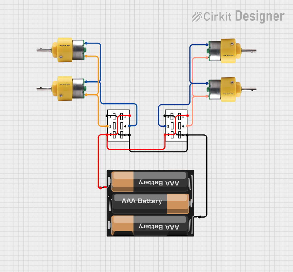
A Double Pole Single Throw (DPST) switch is an electromechanical device that can control two separate circuits simultaneously. This switch has two input terminals and two output terminals, allowing it to connect or disconnect two circuits with a single action. DPST switches are commonly used in applications where it is necessary to control multiple circuits with a single switch, such as in industrial machinery, home appliances, and automotive systems.
Explore Projects Built with Switch DPST


Explore Projects Built with Switch DPST
Technical Specifications
Key Technical Details
| Parameter | Value |
|---|---|
| Voltage Rating | 250V AC |
| Current Rating | 10A |
| Contact Type | Double Pole Single Throw |
| Contact Material | Silver Alloy |
| Insulation Resistance | ≥ 100MΩ at 500V DC |
| Dielectric Strength | 1500V AC for 1 minute |
| Operating Temperature | -25°C to +85°C |
| Mechanical Life | 50,000 cycles |
Pin Configuration and Descriptions
| Pin Number | Description |
|---|---|
| 1 | Input Terminal 1 for Circuit 1 |
| 2 | Output Terminal 1 for Circuit 1 |
| 3 | Input Terminal 2 for Circuit 2 |
| 4 | Output Terminal 2 for Circuit 2 |
Usage Instructions
How to Use the Component in a Circuit
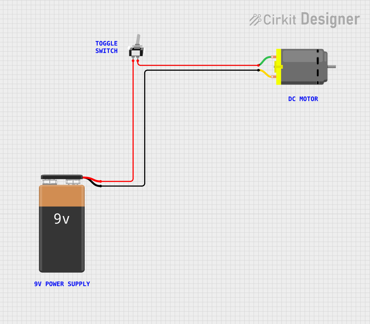
- Identify the Terminals: Locate the four terminals on the DPST switch. Terminals 1 and 2 are for the first circuit, and terminals 3 and 4 are for the second circuit.
- Connect the Input Terminals: Connect the input terminals (1 and 3) to the power sources or the points in the circuits that you want to control.
- Connect the Output Terminals: Connect the output terminals (2 and 4) to the devices or points in the circuits that you want to control.
- Mount the Switch: Securely mount the switch in your desired location, ensuring that it is easily accessible for operation.
- Test the Switch: After making all connections, test the switch by toggling it on and off to ensure that both circuits are being controlled simultaneously.
Important Considerations and Best Practices
- Voltage and Current Ratings: Ensure that the voltage and current ratings of the switch match the requirements of your circuits to avoid damage or malfunction.
- Proper Insulation: Use proper insulation for all connections to prevent short circuits and electrical hazards.
- Mechanical Life: Be aware of the mechanical life of the switch (50,000 cycles) and replace it if it shows signs of wear or malfunction.
- Environmental Conditions: Consider the operating temperature range (-25°C to +85°C) and avoid using the switch in environments that exceed these limits.
Troubleshooting and FAQs
Common Issues Users Might Face
Switch Not Controlling Both Circuits:
- Solution: Check the connections to ensure that both input and output terminals are properly connected. Verify that the switch is not damaged.
Intermittent Operation:
- Solution: Inspect the switch for any signs of wear or damage. Ensure that the connections are secure and that there is no corrosion on the terminals.
Overheating:
- Solution: Ensure that the switch is not being used beyond its rated voltage and current. Check for any short circuits or excessive loads in the connected circuits.
FAQs
Q1: Can I use a DPST switch to control a single circuit?
- A1: Yes, you can use a DPST switch to control a single circuit by connecting only one set of input and output terminals. The other set can remain unconnected.
Q2: Can a DPST switch be used in DC circuits?
- A2: Yes, a DPST switch can be used in DC circuits, but ensure that the voltage and current ratings are suitable for DC applications.
Q3: How do I know if my DPST switch is faulty?
- A3: If the switch does not control the circuits as expected, shows signs of physical damage, or operates intermittently, it may be faulty and should be tested or replaced.
Example Code for Arduino UNO
If you are using a DPST switch with an Arduino UNO to control two LEDs, you can use the following example code:
// Define the pin numbers for the switch and LEDs
const int switchPin = 2; // DPST switch connected to digital pin 2
const int ledPin1 = 9;   // LED 1 connected to digital pin 9
const int ledPin2 = 10;  // LED 2 connected to digital pin 10

void setup() {
  // Initialize the switch pin as an input
  pinMode(switchPin, INPUT);

  // Initialize the LED pins as outputs
  pinMode(ledPin1, OUTPUT);
  pinMode(ledPin2, OUTPUT);
}

void loop() {
  // Read the state of the switch
  int switchState = digitalRead(switchPin);

  // If the switch is pressed, turn on both LEDs
  if (switchState == HIGH) {
    digitalWrite(ledPin1, HIGH);
    digitalWrite(ledPin2, HIGH);
  } else {
    // If the switch is not pressed, turn off both LEDs
    digitalWrite(ledPin1, LOW);
    digitalWrite(ledPin2, LOW);
  }
}
This code reads the state of the DPST switch connected to digital pin 2 of the Arduino UNO. When the switch is pressed, it turns on two LEDs connected to digital pins 9 and 10. When the switch is not pressed, it turns off both LEDs.
By following this documentation, you should be able to effectively use a DPST switch in your electronic projects, ensuring proper operation and troubleshooting any issues that may arise.