Cirkit Designer Logo
Cirkit Designer
Your all-in-one circuit design IDE
Home / 
Component Documentation

How to Use rs232: Examples, Pinouts, and Specs

Image of rs232
Cirkit Designer LogoDesign with rs232 in Cirkit Designer

Introduction

The RS-232 standard is a long-established protocol used for serial communication between devices. It is commonly utilized in computer serial ports and has been widely adopted in industrial and commercial applications. RS-232 facilitates point-to-point data exchange between connected devices.

Explore Projects Built with rs232

Use Cirkit Designer to design, explore, and prototype these projects online. Some projects support real-time simulation. Click "Open Project" to start designing instantly!
Arduino UNO RS232 Serial Communication Interface
Image of Reddit Help - RS232 Serial Communication With Digital Scale: A project utilizing rs232 in a practical application
This circuit connects an Arduino UNO to an RS232 to Serial Converter, allowing the Arduino to communicate with RS232-compatible devices. The Arduino's digital pins D10 and D11 are used for RX and TX communication, respectively, and are interfaced with the corresponding TX and RX pins of the RS232 converter. The embedded code on the Arduino sets up a software serial port for communication with the RS232 converter and relays data between the standard serial port and the software serial port.
Cirkit Designer LogoOpen Project in Cirkit Designer
Satellite-Based Timing and Navigation System with SDR and Atomic Clock Synchronization
Image of GPS 시스템 측정 구성도_Confirm: A project utilizing rs232 in a practical application
This circuit appears to be a complex system involving power supply management, GPS and timing synchronization, and data communication. It includes a SI-TEX G1 Satellite Compass for GPS data, an XHTF1021 Atomic Rubidium Clock for precise timing, and Ettus USRP B200 units for software-defined radio communication. Power is supplied through various SMPS units and distributed via terminal blocks and DC jacks. Data communication is facilitated by Beelink MINI S12 N95 computers, RS232 splitters, and a 1000BASE-T Media Converter for network connectivity. RF Directional Couplers are used to interface antennas with the USRP units, and the entire system is likely contained within cases for protection and organization.
Cirkit Designer LogoOpen Project in Cirkit Designer
FTDI to UART Adapter with J26 Connector
Image of J26 CLOSEUP: A project utilizing rs232 in a practical application
This circuit connects an FTDI USB-to-serial converter to a standard serial interface via a J26 connector. It facilitates serial communication by linking the ground, transmit, receive, data terminal ready, and request to send signals between the FTDI chip and the J26 connector.
Cirkit Designer LogoOpen Project in Cirkit Designer
Satellite Compass and Network-Integrated GPS Data Processing System
Image of GPS 시스템 측정 구성도_241016: A project utilizing rs232 in a practical application
This circuit comprises a satellite compass, a mini PC, two GPS antennas, power supplies, a network switch, media converters, and an atomic rubidium clock. The satellite compass is powered by a triple output DC power supply and interfaces with an RS232 splitter for 1PPS signals. The mini PCs are connected to the USRP B200 devices via USB for data and power, and to media converters via Ethernet, which in turn connect to a network switch using fiber optic links. The antennas are connected to the USRP B200s through RF directional couplers, and the atomic clock provides a 1PPS input to the RS232 splitter.
Cirkit Designer LogoOpen Project in Cirkit Designer

Explore Projects Built with rs232

Use Cirkit Designer to design, explore, and prototype these projects online. Some projects support real-time simulation. Click "Open Project" to start designing instantly!
Image of Reddit Help - RS232 Serial Communication With Digital Scale: A project utilizing rs232 in a practical application
Arduino UNO RS232 Serial Communication Interface
This circuit connects an Arduino UNO to an RS232 to Serial Converter, allowing the Arduino to communicate with RS232-compatible devices. The Arduino's digital pins D10 and D11 are used for RX and TX communication, respectively, and are interfaced with the corresponding TX and RX pins of the RS232 converter. The embedded code on the Arduino sets up a software serial port for communication with the RS232 converter and relays data between the standard serial port and the software serial port.
Cirkit Designer LogoOpen Project in Cirkit Designer
Image of GPS 시스템 측정 구성도_Confirm: A project utilizing rs232 in a practical application
Satellite-Based Timing and Navigation System with SDR and Atomic Clock Synchronization
This circuit appears to be a complex system involving power supply management, GPS and timing synchronization, and data communication. It includes a SI-TEX G1 Satellite Compass for GPS data, an XHTF1021 Atomic Rubidium Clock for precise timing, and Ettus USRP B200 units for software-defined radio communication. Power is supplied through various SMPS units and distributed via terminal blocks and DC jacks. Data communication is facilitated by Beelink MINI S12 N95 computers, RS232 splitters, and a 1000BASE-T Media Converter for network connectivity. RF Directional Couplers are used to interface antennas with the USRP units, and the entire system is likely contained within cases for protection and organization.
Cirkit Designer LogoOpen Project in Cirkit Designer
Image of J26 CLOSEUP: A project utilizing rs232 in a practical application
FTDI to UART Adapter with J26 Connector
This circuit connects an FTDI USB-to-serial converter to a standard serial interface via a J26 connector. It facilitates serial communication by linking the ground, transmit, receive, data terminal ready, and request to send signals between the FTDI chip and the J26 connector.
Cirkit Designer LogoOpen Project in Cirkit Designer
Image of GPS 시스템 측정 구성도_241016: A project utilizing rs232 in a practical application
Satellite Compass and Network-Integrated GPS Data Processing System
This circuit comprises a satellite compass, a mini PC, two GPS antennas, power supplies, a network switch, media converters, and an atomic rubidium clock. The satellite compass is powered by a triple output DC power supply and interfaces with an RS232 splitter for 1PPS signals. The mini PCs are connected to the USRP B200 devices via USB for data and power, and to media converters via Ethernet, which in turn connect to a network switch using fiber optic links. The antennas are connected to the USRP B200s through RF directional couplers, and the atomic clock provides a 1PPS input to the RS232 splitter.
Cirkit Designer LogoOpen Project in Cirkit Designer

Common Applications and Use Cases

  • Serial data transmission between computers and peripherals
  • Modem communication for internet and network connections
  • Industrial control systems
  • GPS receivers
  • Point-of-sale systems
  • CNC machines and other manufacturing equipment

Technical Specifications

Key Technical Details

  • Voltage Levels: Logic '1' (-15V to -3V), Logic '0' (+3V to +15V)
  • Data Rate: Up to 115.2 kbps (kilobits per second)
  • Maximum Cable Length: 50 feet (15 meters) at highest speeds, longer at lower speeds
  • Connector Types: DB9 and DB25 are the most common

Pin Configuration and Descriptions

The following table describes the pin configuration for a standard DB9 RS-232 connector:

Pin Number Signal Name Description
1 DCD Data Carrier Detect
2 RXD Received Data
3 TXD Transmitted Data
4 DTR Data Terminal Ready
5 GND Signal Ground
6 DSR Data Set Ready
7 RTS Request To Send
8 CTS Clear To Send
9 RI Ring Indicator

Usage Instructions

How to Use the RS-232 in a Circuit

  1. Connection: Connect the RS-232 module to the device using a DB9 or DB25 cable, ensuring that the TXD and RXD pins are correctly aligned with the corresponding pins on the device.
  2. Power Supply: Ensure that the RS-232 module is powered with the correct voltage levels as per the module's specifications.
  3. Configuration: Set the baud rate and other communication parameters to match the settings of both communicating devices.
  4. Data Transmission: Initiate communication by sending data from the TXD pin and receiving data on the RXD pin.

Important Considerations and Best Practices

  • Cable Quality: Use high-quality cables to minimize signal degradation over longer distances.
  • Grounding: Ensure proper grounding to avoid potential differences that can cause communication errors.
  • Interference: Avoid running RS-232 cables near high-voltage or high-current lines to prevent electromagnetic interference.
  • Baud Rate Matching: Both devices must be configured to use the same baud rate for successful communication.

Troubleshooting and FAQs

Common Issues

  • No Communication: Check connections, ensure correct pin alignment, and verify that both devices are powered on.
  • Garbled Data: Confirm that the baud rate and other communication settings match on both devices.
  • Intermittent Communication: Inspect cables for damage and ensure secure connections.

Solutions and Tips for Troubleshooting

  • Signal Testing: Use an oscilloscope or a logic analyzer to test the signals at the RS-232 output pins.
  • Cable Replacement: If a cable is suspected to be faulty, replace it with a new one and retest the communication.
  • Device Configuration: Double-check the configuration settings on both devices for any discrepancies.

FAQs

Q: Can RS-232 be used for networking multiple devices? A: RS-232 is designed for point-to-point communication. For networking multiple devices, consider using protocols like RS-485 or Ethernet.

Q: What is the maximum distance for RS-232 communication? A: The maximum recommended distance is 50 feet at higher speeds, but it can be extended at lower baud rates with high-quality cabling.

Q: How can I connect an RS-232 device to a USB port? A: Use an RS-232 to USB converter or adapter to connect an RS-232 device to a USB port.

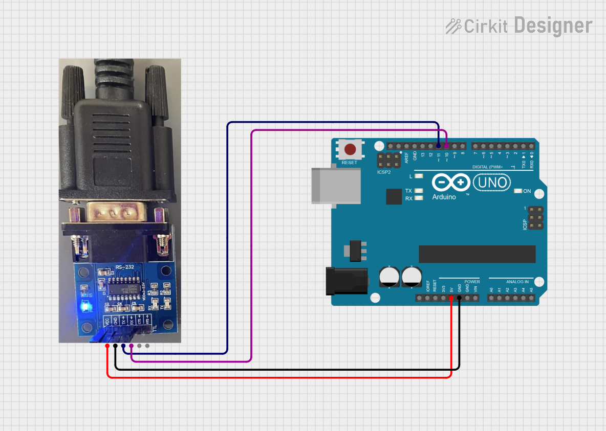
Example Code for Arduino UNO

Below is an example of how to set up serial communication between an Arduino UNO and an RS-232 device.

#include <SoftwareSerial.h>

// RX and TX pins for the Arduino connected to the RS-232 module
const int rxPin = 10;
const int txPin = 11;

// Set up a new SoftwareSerial port
SoftwareSerial rs232Serial(rxPin, txPin);

void setup() {
  // Start the built-in hardware serial port
  Serial.begin(9600);
  // Start the RS-232 serial port
  rs232Serial.begin(9600);
  Serial.println("RS-232 Serial communication started.");
}

void loop() {
  // Check if data has been received from the RS-232 device
  if (rs232Serial.available()) {
    int inByte = rs232Serial.read();
    // Send the byte to the hardware serial port
    Serial.write(inByte);
  }
  
  // Check if data has been received from the hardware serial port
  if (Serial.available()) {
    int inByte = Serial.read();
    // Send the byte to the RS-232 device
    rs232Serial.write(inByte);
  }
}

Note: The SoftwareSerial library is used to create a serial communication port on digital pins 10 and 11, as the Arduino UNO has only one hardware serial port, which is often used for debugging and uploading code. Ensure that the baud rate in the begin() function matches the RS-232 device's settings.