Cirkit Designer
Your all-in-one circuit design IDE
Home /
Component Documentation
How to Use ESP32_30Pin_蓝色电源模块: Examples, Pinouts, and Specs
Introduction
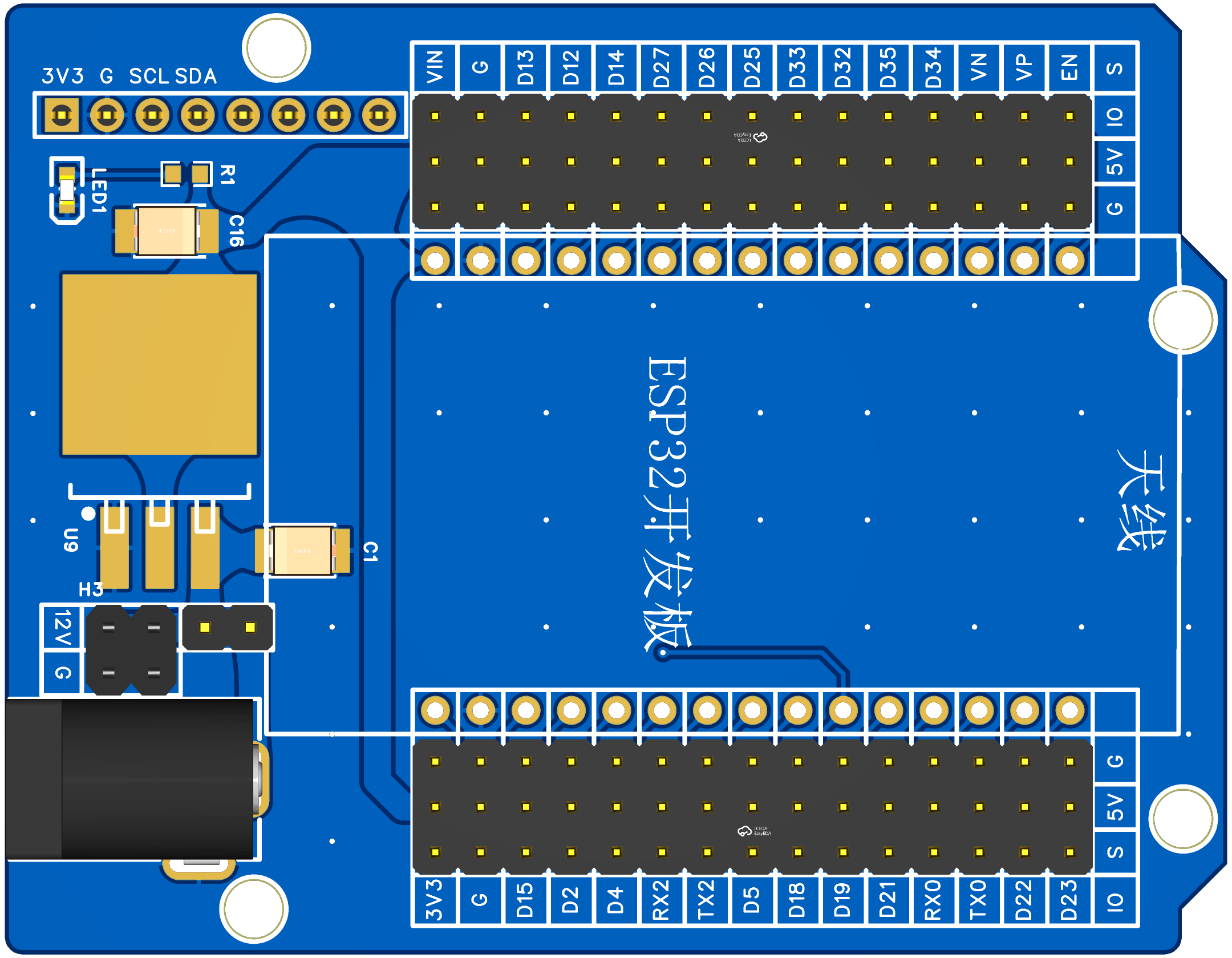
The ESP32_30Pin_蓝色电源模块 by SRYY (Part ID: ESP32_UNO尺寸蓝色电源板) is a versatile microcontroller module featuring 30 pins, Wi-Fi, and Bluetooth capabilities. This module is widely used in Internet of Things (IoT) applications, prototyping, and various embedded systems projects. Its compatibility with the Arduino IDE makes it a popular choice among hobbyists and professionals alike.
Explore Projects Built with ESP32_30Pin_蓝色电源模块
ESP32-Controlled AC Lighting System with Power Monitoring

This circuit features an ESP32 microcontroller interfaced with a PZEM004T power monitoring module and a 4-channel relay module controlling multiple AC LED bulbs. The ESP32 uses GPIO pins to control the relays, which in turn switch the LED bulbs on and off. The PZEM004T is connected to the ESP32 for communication and to a current sensor for monitoring power consumption of the connected load through the relay contacts.
ESP32-Controlled Multi-Color LED Array with GSM and GPS Functionality
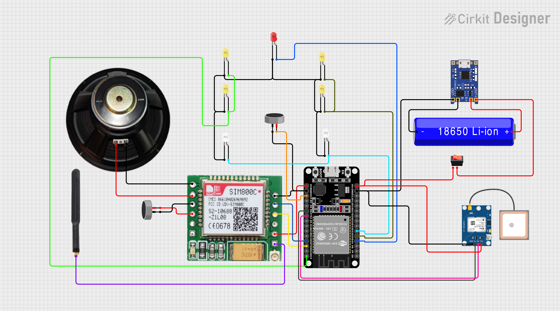
This circuit features an ESP32 microcontroller connected to multiple LEDs, a SIM800c GSM module with a speaker and microphone for audio input/output, and a GPS NEO 6M module for location tracking. The ESP32 controls the LEDs and communicates with the GSM and GPS modules via serial connections. Power management is handled by a TP4056 charging module connected to a 18650 Li-ion battery, with a rocker switch to control power flow.
ESP32-Based Audio Player with LED Indicators and Battery Charging
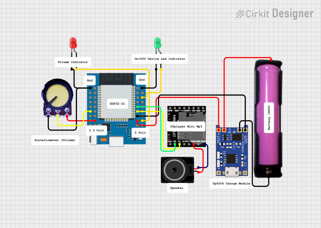
This circuit features an ESP32 Mini microcontroller connected to a DFPlayer Mini MP3 module for audio playback, with a loudspeaker attached for sound output. The ESP32 controls two LEDs (green and red) and reads an analog value from a potentiometer. Power management is handled by a TP4056 charging module connected to an 18650 battery, providing power to the ESP32 and other components.
ESP32 and HM-10 Bluetooth Module Communication System
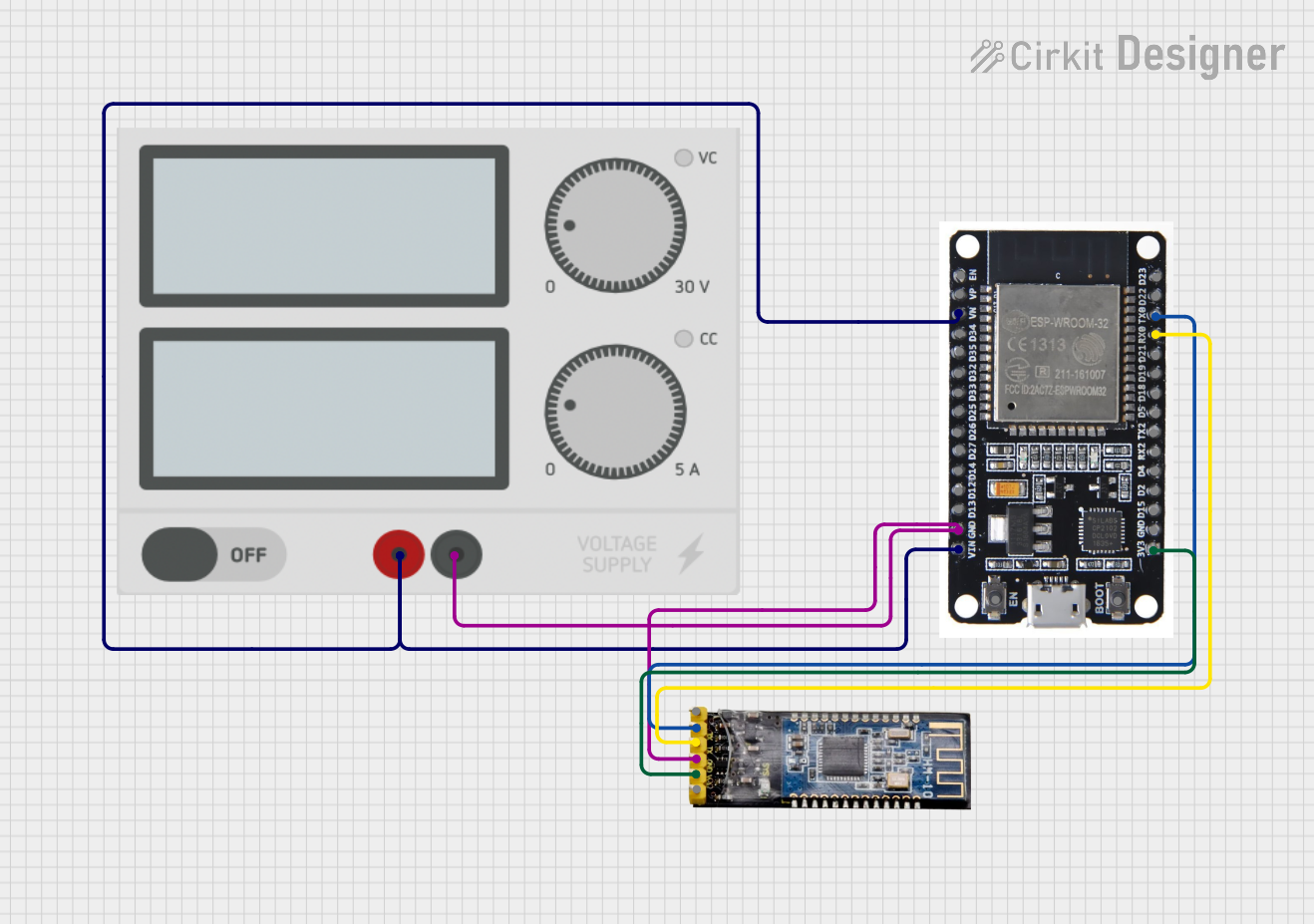
This circuit integrates an ESP32 microcontroller with an HM-10 Bluetooth module, powered by an external power supply. The ESP32 communicates with the Bluetooth module via UART, enabling wireless data transmission.
Explore Projects Built with ESP32_30Pin_蓝色电源模块
ESP32-Controlled AC Lighting System with Power Monitoring
This circuit features an ESP32 microcontroller interfaced with a PZEM004T power monitoring module and a 4-channel relay module controlling multiple AC LED bulbs. The ESP32 uses GPIO pins to control the relays, which in turn switch the LED bulbs on and off. The PZEM004T is connected to the ESP32 for communication and to a current sensor for monitoring power consumption of the connected load through the relay contacts.
ESP32-Controlled Multi-Color LED Array with GSM and GPS Functionality
This circuit features an ESP32 microcontroller connected to multiple LEDs, a SIM800c GSM module with a speaker and microphone for audio input/output, and a GPS NEO 6M module for location tracking. The ESP32 controls the LEDs and communicates with the GSM and GPS modules via serial connections. Power management is handled by a TP4056 charging module connected to a 18650 Li-ion battery, with a rocker switch to control power flow.
ESP32-Based Audio Player with LED Indicators and Battery Charging
This circuit features an ESP32 Mini microcontroller connected to a DFPlayer Mini MP3 module for audio playback, with a loudspeaker attached for sound output. The ESP32 controls two LEDs (green and red) and reads an analog value from a potentiometer. Power management is handled by a TP4056 charging module connected to an 18650 battery, providing power to the ESP32 and other components.
ESP32 and HM-10 Bluetooth Module Communication System
This circuit integrates an ESP32 microcontroller with an HM-10 Bluetooth module, powered by an external power supply. The ESP32 communicates with the Bluetooth module via UART, enabling wireless data transmission.
Technical Specifications
Key Technical Details
| Parameter | Value |
|---|---|
| Microcontroller | ESP32 |
| Operating Voltage | 3.3V |
| Input Voltage | 5V (via USB) |
| Digital I/O Pins | 30 |
| Analog Input Pins | 16 |
| Flash Memory | 4MB |
| Wi-Fi | 802.11 b/g/n |
| Bluetooth | v4.2 BR/EDR and BLE |
| Operating Temperature | -40°C to 85°C |
Pin Configuration and Descriptions
| Pin Number | Pin Name | Description |
|---|---|---|
| 1 | EN | Enable pin (active high) |
| 2 | IO23 | GPIO23 |
| 3 | IO22 | GPIO22 |
| 4 | TXD0 | UART0 Transmit |
| 5 | RXD0 | UART0 Receive |
| 6 | IO21 | GPIO21 |
| 7 | GND | Ground |
| 8 | IO19 | GPIO19 |
| 9 | IO18 | GPIO18 |
| 10 | IO5 | GPIO5 |
| 11 | IO17 | GPIO17 |
| 12 | IO16 | GPIO16 |
| 13 | IO4 | GPIO4 |
| 14 | IO0 | GPIO0 |
| 15 | IO2 | GPIO2 |
| 16 | IO15 | GPIO15 |
| 17 | IO13 | GPIO13 |
| 18 | IO12 | GPIO12 |
| 19 | IO14 | GPIO14 |
| 20 | IO27 | GPIO27 |
| 21 | IO26 | GPIO26 |
| 22 | IO25 | GPIO25 |
| 23 | IO33 | GPIO33 |
| 24 | IO32 | GPIO32 |
| 25 | IO35 | GPIO35 (input only) |
| 26 | IO34 | GPIO34 (input only) |
| 27 | IO39 | GPIO39 (input only) |
| 28 | IO36 | GPIO36 (input only) |
| 29 | 3V3 | 3.3V power output |
| 30 | VIN | 5V input (via USB) |
Usage Instructions
How to Use the Component in a Circuit
Powering the Module:
- Connect the VIN pin to a 5V power source (e.g., USB).
- Ensure the GND pin is connected to the ground of the power source.
Programming the Module:
- Connect the module to your computer using a USB cable.
- Open the Arduino IDE and select "ESP32 Dev Module" from the board manager.
- Write your code and upload it to the module.
Connecting Peripherals:
- Use the GPIO pins to connect sensors, actuators, and other peripherals.
- Ensure the peripherals are compatible with the 3.3V logic level of the ESP32.
Important Considerations and Best Practices
- Voltage Levels: Ensure all connected peripherals operate at 3.3V to avoid damaging the ESP32.
- Heat Management: The ESP32 can get warm during operation. Ensure proper ventilation or use a heat sink if necessary.
- Pin Multiplexing: Some pins have multiple functions (e.g., ADC, UART). Refer to the ESP32 datasheet for detailed pin functions.
Example Code for Arduino UNO
// Example code to blink an LED connected to GPIO2

void setup() {
  // Initialize GPIO2 as an output pin
  pinMode(2, OUTPUT);
}

void loop() {
  // Turn the LED on
  digitalWrite(2, HIGH);
  delay(1000); // Wait for 1 second

  // Turn the LED off
  digitalWrite(2, LOW);
  delay(1000); // Wait for 1 second
}
Troubleshooting and FAQs
Common Issues Users Might Face
Module Not Detected by Computer:
- Ensure the USB cable is properly connected.
- Try a different USB cable or port.
- Install the necessary drivers for the ESP32.
Upload Errors in Arduino IDE:
- Check the selected board and port in the Arduino IDE.
- Press and hold the "EN" button on the module while uploading.
Wi-Fi Connection Issues:
- Ensure the correct SSID and password are used.
- Check the Wi-Fi signal strength and reduce the distance to the router.
Solutions and Tips for Troubleshooting
- Serial Monitor: Use the Serial Monitor in the Arduino IDE to debug and print error messages.
- Power Supply: Ensure a stable power supply. Unstable power can cause unexpected behavior.
- Firmware Updates: Keep the ESP32 firmware updated to the latest version for improved performance and bug fixes.
By following this documentation, users can effectively utilize the ESP32_30Pin_蓝色电源模块 in their projects, ensuring optimal performance and reliability.