How to Use Key switch: Examples, Pinouts, and Specs

Introduction
A key switch is a mechanical or electronic switch that is activated by pressing a key. It is widely used in devices such as keyboards, control panels, and industrial equipment to enable or disable circuits. Key switches are valued for their tactile feedback, durability, and reliability in applications requiring frequent actuation. They come in various types, including mechanical, membrane, and capacitive switches, each suited for specific use cases.
Explore Projects Built with Key switch

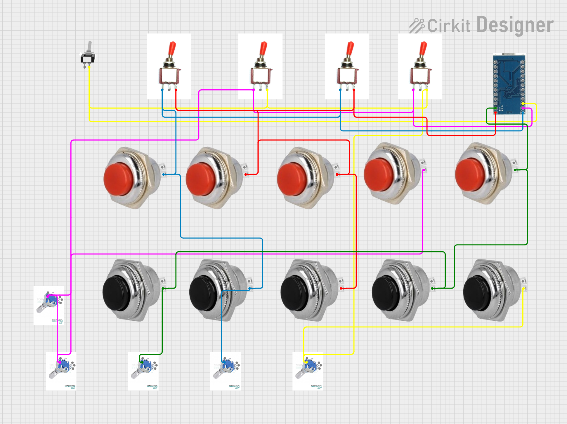
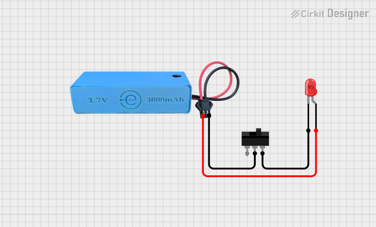
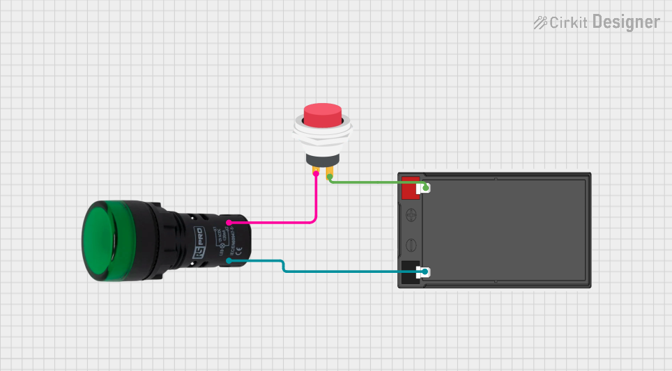
Explore Projects Built with Key switch
Common Applications and Use Cases
- Computer keyboards and gaming peripherals
- Control panels for industrial machinery
- Security systems and access control
- Elevator control panels
- Custom electronics projects requiring user input
Technical Specifications
Key switches vary in design and specifications depending on their type and intended application. Below are general technical details for a typical mechanical key switch:
| Parameter | Value |
|---|---|
| Actuation Force | 45g to 60g (varies by model) |
| Actuation Point | 2.0 mm to 2.2 mm |
| Total Travel Distance | 4.0 mm |
| Rated Voltage | 5V DC (typical for electronic use) |
| Rated Current | 10 mA to 50 mA |
| Contact Resistance | < 200 mΩ |
| Lifespan | 50 million keystrokes (typical) |
| Operating Temperature | -10°C to 70°C |
Pin Configuration and Descriptions
Key switches typically have two pins for electrical connections. The table below describes the pin configuration:
| Pin | Description |
|---|---|
| Pin 1 | Connected to the circuit's input or power source |
| Pin 2 | Connected to the circuit's ground or signal line |
Note: Some key switches may include additional pins for features like LED backlighting.
Usage Instructions
How to Use the Component in a Circuit
- Identify the Pins: Determine the two pins of the key switch. Use a multimeter to confirm continuity when the switch is pressed.
- Connect to Circuit:
- Connect one pin to the input signal or power source.
- Connect the other pin to the ground or signal line of the circuit.
- Debounce the Signal: Mechanical key switches may produce noise or "bouncing" when pressed. Use a capacitor or software debounce logic to stabilize the signal.
- Test the Circuit: Verify that the key switch operates as expected by pressing it and observing the circuit's response.
Important Considerations and Best Practices
- Debouncing: Always implement hardware or software debouncing to avoid erratic behavior.
- Current Limiting: Ensure the current through the switch does not exceed its rated value to prevent damage.
- Mounting: Secure the key switch properly to avoid mechanical stress or misalignment.
- Environmental Conditions: Use key switches rated for the operating temperature and humidity of your application.
Example: Using a Key Switch with Arduino UNO
Below is an example of how to connect and use a key switch with an Arduino UNO:
Circuit Diagram
- Connect one pin of the key switch to digital pin 2 on the Arduino.
- Connect the other pin to the ground (GND).
- Use a pull-up resistor (10kΩ) between the input pin and 5V to ensure a stable signal.
Code Example
// Key Switch Example with Arduino UNO
// This code reads the state of a key switch and turns on an LED when pressed.

const int keySwitchPin = 2; // Pin connected to the key switch
const int ledPin = 13;      // Pin connected to the onboard LED

void setup() {
  pinMode(keySwitchPin, INPUT_PULLUP); // Set key switch pin as input with pull-up
  pinMode(ledPin, OUTPUT);            // Set LED pin as output
}

void loop() {
  int keyState = digitalRead(keySwitchPin); // Read the key switch state

  if (keyState == LOW) { // Key switch is pressed (LOW due to pull-up resistor)
    digitalWrite(ledPin, HIGH); // Turn on the LED
  } else {
    digitalWrite(ledPin, LOW);  // Turn off the LED
  }
}
Troubleshooting and FAQs
Common Issues and Solutions
Key Switch Not Responding
- Cause: Loose or incorrect wiring.
- Solution: Check the connections and ensure the pins are properly soldered or secured.
Erratic Behavior (Multiple Signals)
- Cause: Signal bouncing due to mechanical contacts.
- Solution: Add a capacitor (e.g., 0.1 µF) across the pins or implement software debouncing.
Switch Feels Stiff or Unresponsive
- Cause: Dirt or debris inside the switch.
- Solution: Clean the switch with compressed air or contact cleaner.
LED Not Turning On in Arduino Example
- Cause: Incorrect pin configuration or faulty key switch.
- Solution: Verify the pin assignments in the code and test the key switch with a multimeter.
FAQs
Q: Can I use a key switch for high-current applications?
A: No, key switches are typically designed for low-current applications. Use a relay or transistor to handle higher currents.
Q: How do I know if my key switch is working?
A: Use a multimeter to check for continuity between the pins when the switch is pressed.
Q: What is the difference between a mechanical and membrane key switch?
A: Mechanical key switches use physical contacts for actuation, providing tactile feedback and durability. Membrane switches use pressure pads and are generally quieter but less durable.
Q: Can I use a key switch with a Raspberry Pi?
A: Yes, you can connect a key switch to a GPIO pin on a Raspberry Pi. Use a pull-up or pull-down resistor to stabilize the signal.