How to Use Adaruit DS3231: Examples, Pinouts, and Specs
Introduction
The Adafruit DS3231 is a precision real-time clock (RTC) module that maintains accurate timekeeping even when the main power to the device it's connected to is turned off. Utilizing a temperature-compensated crystal oscillator, the DS3231 provides high stability and accuracy. Common applications include timekeeping in embedded systems, data logging with timestamps, and scheduling in various electronic projects.
Explore Projects Built with Adaruit DS3231
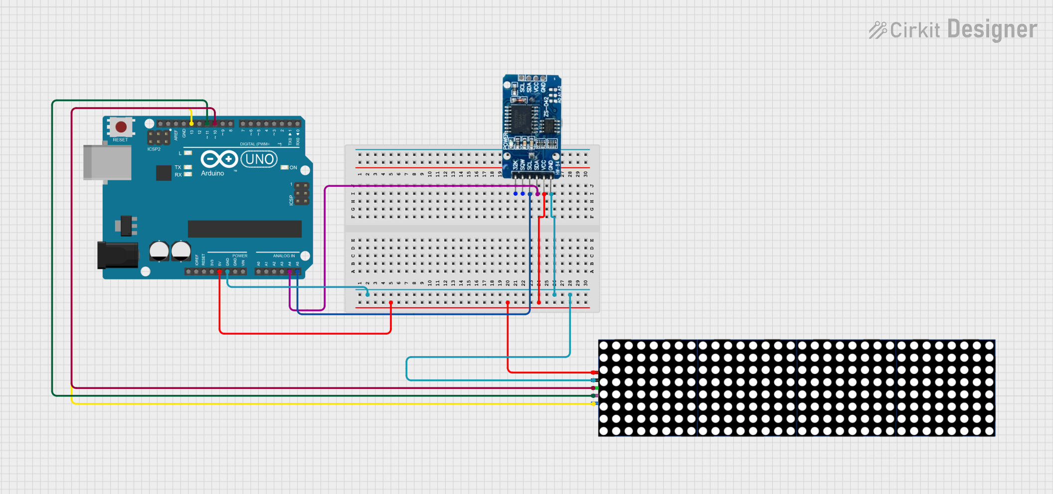

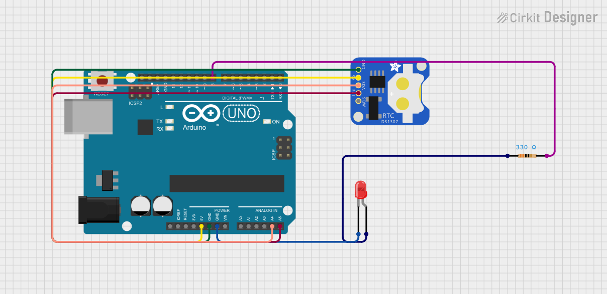
Explore Projects Built with Adaruit DS3231
Technical Specifications
Key Technical Details
- Time Accuracy: ±2ppm from 0°C to +40°C
- Battery Backup: Yes (CR2032 coin cell)
- Communication: I2C interface
- Operating Voltage: 2.3V to 5.5V
- Operating Temperature: -40°C to +85°C
- Memory: 236 bytes of non-volatile RAM
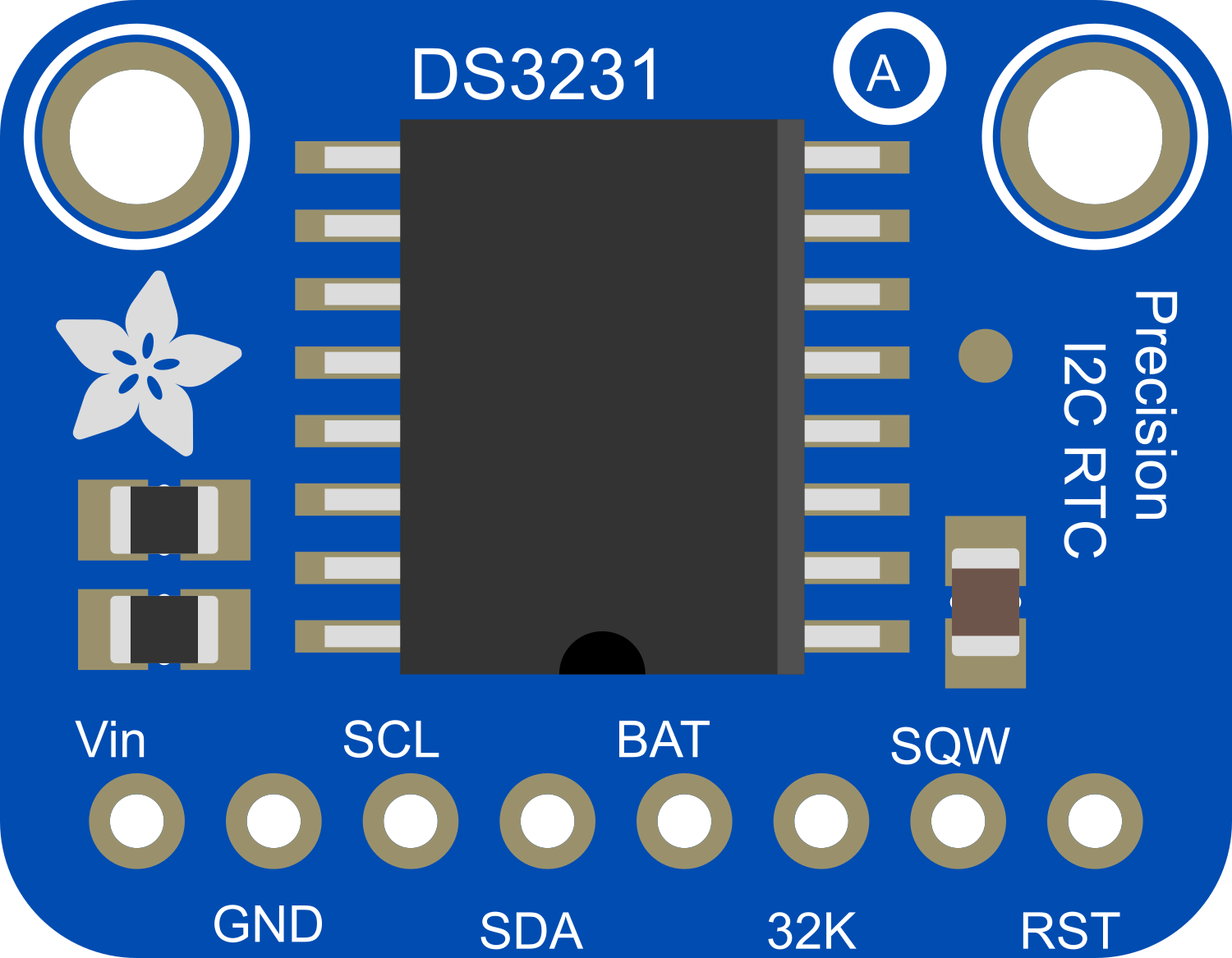
Pin Configuration and Descriptions
| Pin Number | Name | Description |
|---|---|---|
| 1 | VCC | Power supply (2.3V to 5.5V) |
| 2 | GND | Ground connection |
| 3 | SDA | I2C Data line |
| 4 | SCL | I2C Clock line |
| 5 | SQW | Square Wave/Interrupt output |
| 6 | 32K | 32kHz Output |
| 7 | RST | Reset input (active low) |
Usage Instructions
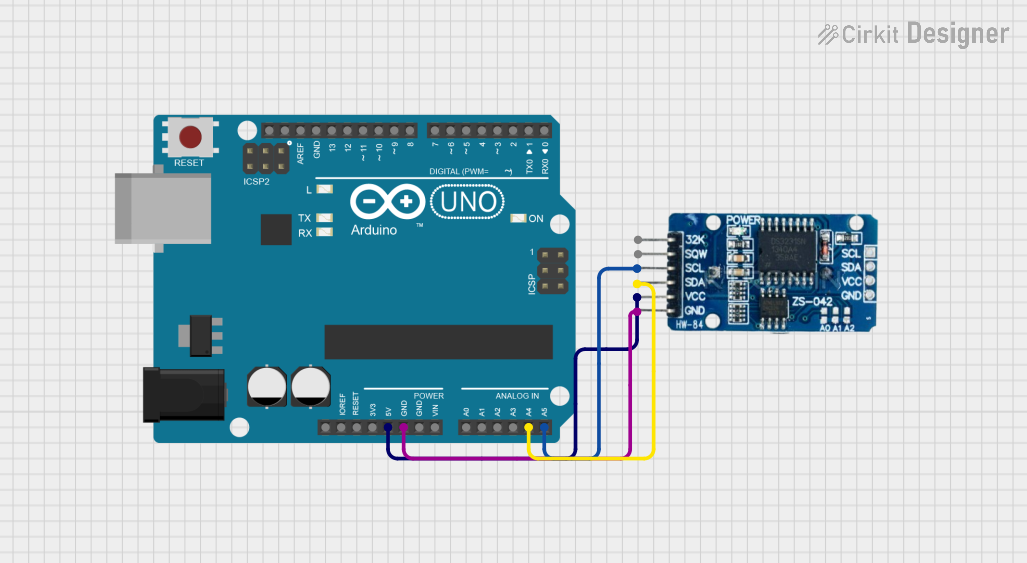
Integrating with a Circuit
- Power Connections: Connect VCC to a 2.3V to 5.5V power supply and GND to the ground.
- I2C Connections: Connect SDA and SCL to your microcontroller's I2C data and clock lines respectively. For Arduino UNO, SDA is A4 and SCL is A5.
- Battery Backup: Insert a CR2032 coin cell battery to keep the RTC running when main power is lost.
- Square Wave/Interrupts: Optionally, use the SQW pin for generating square waves or as an interrupt signal.
- 32kHz Output: Optionally, use the 32K pin if a 32kHz reference signal is required.
Important Considerations and Best Practices
- Ensure that the I2C bus has pull-up resistors as required for your microcontroller.
- Avoid placing the module near heat sources to prevent temperature-induced inaccuracies.
- When using battery backup, be mindful of the battery's shelf life and replace it as needed.
Example Code for Arduino UNO
#include <Wire.h>
#include <RTClib.h>

RTC_DS3231 rtc;

void setup() {
  Serial.begin(9600);

  // Check if the RTC is connected correctly
  if (!rtc.begin()) {
    Serial.println("Couldn't find RTC");
    while (1);
  }

  // Check if the RTC lost power and if so, set the time
  if (rtc.lostPower()) {
    Serial.println("RTC lost power, setting the time!");
    // The following line sets the RTC to the date & time this sketch was compiled
    rtc.adjust(DateTime(F(__DATE__), F(__TIME__)));
  }
}

void loop() {
  DateTime now = rtc.now();

  // Print the current date and time
  Serial.print(now.year(), DEC);
  Serial.print('/');
  Serial.print(now.month(), DEC);
  Serial.print('/');
  Serial.print(now.day(), DEC);
  Serial.print(" ");
  Serial.print(now.hour(), DEC);
  Serial.print(':');
  Serial.print(now.minute(), DEC);
  Serial.print(':');
  Serial.print(now.second(), DEC);
  Serial.println();

  // Wait for a second
  delay(1000);
}
Troubleshooting and FAQs
Common Issues
- Time Not Accurate: Ensure the RTC module is not exposed to extreme temperatures and that the battery is in good condition.
- I2C Communication Failure: Check the wiring, ensure pull-up resistors are in place, and verify that the correct I2C address is being used.
- Module Not Responding: Make sure the power supply is within the specified range and the battery is properly installed.
Solutions and Tips for Troubleshooting
- Battery Issues: Replace the CR2032 coin cell if the RTC has lost power or is not maintaining time when the main power supply is disconnected.
- I2C Scanning: Use an I2C scanner sketch to ensure that the Arduino is detecting the RTC module.
- Resetting the Module: If the module is not functioning as expected, a reset can be performed by pulling the RST pin low.
FAQs
Q: How do I set the time on the DS3231?
A: The time can be set using the rtc.adjust(DateTime(...)); function in the Arduino sketch.
Q: Can the DS3231 be used in low-power applications? A: Yes, the DS3231 has a very low power consumption, especially when running off the backup battery.
Q: What is the purpose of the 32K pin? A: The 32K pin outputs a 32kHz square wave that can be used as a clock reference for other devices.