How to Use Stepper Motor Driver (LCDA257S): Examples, Pinouts, and Specs
Introduction
The LCDA257S is a specialized driver designed for controlling stepper motors with high precision. It enables accurate control over motor position, speed, and direction, making it an essential component in applications requiring precise movement. Commonly used in robotics, CNC machines, 3D printers, and automated systems, the LCDA257S ensures smooth and reliable operation of stepper motors.
Key features of the LCDA257S include microstepping capability, adjustable current control, and built-in protection mechanisms, making it suitable for a wide range of industrial and hobbyist projects.
Explore Projects Built with Stepper Motor Driver (LCDA257S)


Explore Projects Built with Stepper Motor Driver (LCDA257S)
Technical Specifications
Below are the key technical details of the LCDA257S stepper motor driver:
- Input Voltage Range: 8V to 35V DC
- Output Current: Up to 2.5A per phase
- Microstepping Modes: Full step, 1/2 step, 1/4 step, 1/8 step, 1/16 step
- Control Interface: Step and direction signals
- Protection Features: Overcurrent, overtemperature, and undervoltage lockout
- Operating Temperature: -20°C to 85°C
- Dimensions: 42mm x 20mm x 15mm
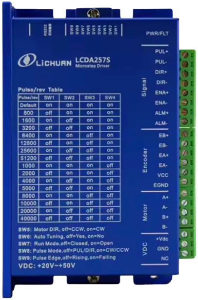
Pin Configuration and Descriptions
The LCDA257S has a standard pinout for easy integration into circuits. Below is the pin configuration:
| Pin Name | Type | Description |
|---|---|---|
| VCC | Power Input | Connect to a DC power supply (8V to 35V). |
| GND | Power Ground | Ground connection for the power supply and logic signals. |
| STEP | Logic Input | Receives step pulses to control motor movement. |
| DIR | Logic Input | Determines the direction of motor rotation (high = clockwise, low = counterclockwise). |
| EN | Logic Input | Enable pin; active low. Pull low to enable the driver, high to disable it. |
| A+ | Motor Output | Connect to one terminal of the motor's A coil. |
| A- | Motor Output | Connect to the other terminal of the motor's A coil. |
| B+ | Motor Output | Connect to one terminal of the motor's B coil. |
| B- | Motor Output | Connect to the other terminal of the motor's B coil. |
Usage Instructions
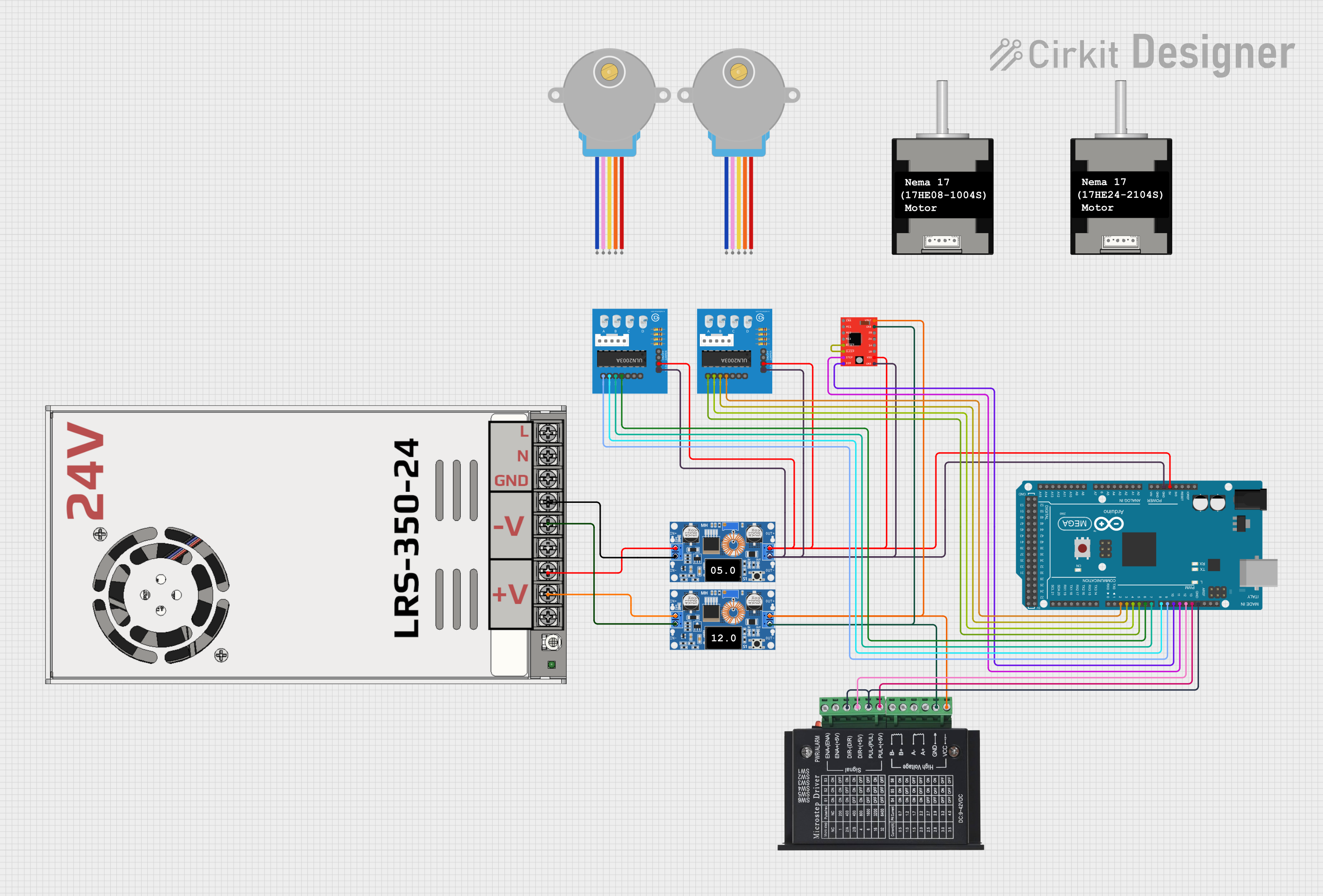
How to Use the LCDA257S in a Circuit
- Power Supply: Connect the VCC pin to a DC power supply within the range of 8V to 35V. Ensure the power supply can provide sufficient current for the motor.
- Motor Connections: Connect the stepper motor's coils to the A+/- and B+/- pins. Refer to the motor's datasheet to identify the correct coil pairs.
- Control Signals:
- Connect the STEP and DIR pins to a microcontroller or other control circuit.
- Use the EN pin to enable or disable the driver as needed.
- Microstepping Configuration: Configure the microstepping mode using external jumpers or resistors (refer to the LCDA257S datasheet for details).
- Heat Dissipation: If operating at high currents, attach a heatsink to the driver to prevent overheating.
Arduino UNO Example Code
Below is an example of how to control the LCDA257S with an Arduino UNO:
// Define pin connections
const int stepPin = 3;  // STEP pin connected to Arduino digital pin 3
const int dirPin = 4;   // DIR pin connected to Arduino digital pin 4
const int enPin = 5;    // EN pin connected to Arduino digital pin 5

void setup() {
  // Set pin modes
  pinMode(stepPin, OUTPUT);
  pinMode(dirPin, OUTPUT);
  pinMode(enPin, OUTPUT);

  // Enable the driver
  digitalWrite(enPin, LOW);  // Active low to enable the driver
}

void loop() {
  // Set direction to clockwise
  digitalWrite(dirPin, HIGH);

  // Generate step pulses
  for (int i = 0; i < 200; i++) {  // 200 steps for one revolution (1.8°/step motor)
    digitalWrite(stepPin, HIGH);
    delayMicroseconds(500);  // 500 µs pulse width
    digitalWrite(stepPin, LOW);
    delayMicroseconds(500);  // 500 µs delay between pulses
  }

  delay(1000);  // Wait 1 second

  // Set direction to counterclockwise
  digitalWrite(dirPin, LOW);

  // Generate step pulses
  for (int i = 0; i < 200; i++) {
    digitalWrite(stepPin, HIGH);
    delayMicroseconds(500);
    digitalWrite(stepPin, LOW);
    delayMicroseconds(500);
  }

  delay(1000);  // Wait 1 second
}
Important Considerations
- Current Limiting: Adjust the current limit on the LCDA257S to match the stepper motor's rated current. This prevents overheating and damage to the motor.
- Decoupling Capacitors: Place a decoupling capacitor (e.g., 100µF) near the VCC and GND pins to stabilize the power supply.
- Signal Integrity: Use short, shielded wires for STEP and DIR signals to minimize noise and ensure reliable operation.
Troubleshooting and FAQs
Common Issues and Solutions
Motor Not Moving:
- Verify the power supply voltage and current are within the specified range.
- Check the STEP and DIR signal connections and ensure the microcontroller is generating pulses.
- Ensure the EN pin is pulled low to enable the driver.
Motor Vibrates but Does Not Rotate:
- Check the motor coil connections (A+/- and B+/-). Incorrect wiring can cause this issue.
- Verify the microstepping configuration and adjust if necessary.
Driver Overheating:
- Ensure the current limit is set correctly for the motor.
- Attach a heatsink or improve ventilation around the driver.
Erratic Motor Movement:
- Check for noise or interference on the STEP and DIR signals.
- Use pull-up or pull-down resistors on control pins if needed.
FAQs
Can I use the LCDA257S with a 12V power supply? Yes, the LCDA257S supports input voltages from 8V to 35V, so a 12V power supply is suitable.
What is the maximum step rate supported? The LCDA257S can handle step rates up to 200kHz, depending on the motor and system configuration.
Do I need a heatsink for the LCDA257S? A heatsink is recommended if the driver operates at high currents (above 1.5A) for extended periods.
By following this documentation, you can effectively integrate the LCDA257S into your projects and achieve precise control of stepper motors.