How to Use DRIVER MOTOR DM542: Examples, Pinouts, and Specs
Introduction
The DM542 is a digital stepper motor driver manufactured by SIFA LAB, designed to provide precise control of stepper motors. It supports microstepping, enabling smoother operation and higher resolution for stepper motors. The DM542 is compatible with a wide range of input voltages and currents, making it versatile for use in robotics, CNC machines, 3D printers, and other automation systems. Its robust design ensures reliable performance in demanding applications.
Explore Projects Built with DRIVER MOTOR DM542


Explore Projects Built with DRIVER MOTOR DM542
Technical Specifications
The DM542 offers a range of features and specifications that make it suitable for various stepper motor control applications.
Key Specifications
- Input Voltage: 18V to 50V DC
- Output Current: 1.0A to 4.2A (adjustable)
- Microstepping Resolution: Up to 1/128 steps
- Control Signal Voltage: 5V (compatible with TTL logic)
- Pulse Frequency: Up to 200 kHz
- Operating Temperature: -10°C to +45°C
- Protection Features: Over-voltage, under-voltage, and over-current protection
Pin Configuration and Descriptions
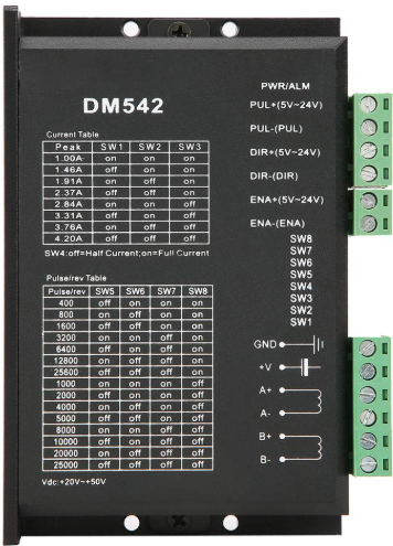
The DM542 has a set of input and output terminals for connecting to the power supply, stepper motor, and control signals. Below is the pin configuration:
Power and Motor Connections
| Pin Name | Description |
|---|---|
| V+ | Positive terminal for DC power input |
| V- | Negative terminal for DC power input |
| A+ | Positive terminal for motor coil A |
| A- | Negative terminal for motor coil A |
| B+ | Positive terminal for motor coil B |
| B- | Negative terminal for motor coil B |
Control Signal Connections
| Pin Name | Description |
|---|---|
| PUL+ | Positive terminal for pulse signal (step input) |
| PUL- | Negative terminal for pulse signal (step input) |
| DIR+ | Positive terminal for direction signal |
| DIR- | Negative terminal for direction signal |
| ENA+ | Positive terminal for enable signal (optional, used to enable/disable driver) |
| ENA- | Negative terminal for enable signal (optional, used to enable/disable driver) |
Usage Instructions
How to Use the DM542 in a Circuit
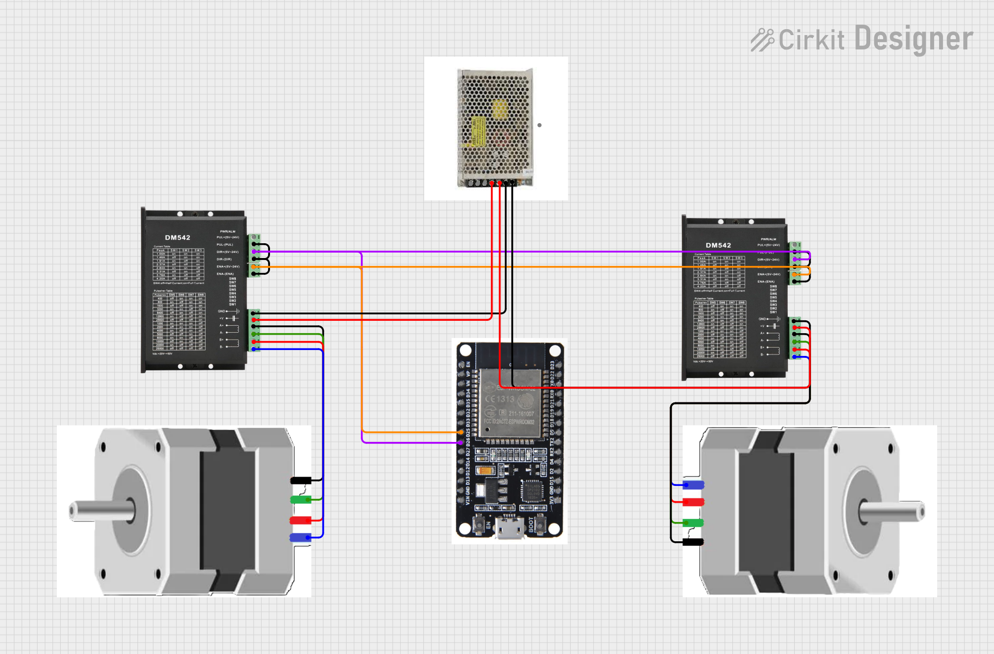
- Power Supply: Connect a DC power supply (18V to 50V) to the V+ and V- terminals. Ensure the power supply can provide sufficient current for the stepper motor.
- Motor Connection: Connect the stepper motor coils to the A+, A-, B+, and B- terminals. Refer to the motor's datasheet to identify the correct coil pairs.
- Control Signals: Connect the PUL+, PUL-, DIR+, DIR-, ENA+, and ENA- terminals to a microcontroller or control system. For example, an Arduino UNO can be used to generate the pulse and direction signals.
- Microstepping Configuration: Use the DIP switches on the DM542 to set the desired microstepping resolution and output current. Refer to the DM542 datasheet for the DIP switch settings.
- Enable the Driver: If the enable signal is used, ensure it is set to the appropriate logic level to activate the driver.
Important Considerations and Best Practices
- Current Setting: Adjust the output current using the DIP switches to match the stepper motor's rated current. Overdriving the motor can cause overheating or damage.
- Signal Quality: Use shielded cables for control signals to minimize noise and ensure reliable operation.
- Cooling: Ensure adequate ventilation or cooling for the DM542, especially in high-current applications.
- Power Supply: Use a stable and regulated power supply to avoid voltage fluctuations that could affect performance.
Example: Connecting the DM542 to an Arduino UNO
Below is an example Arduino sketch to control a stepper motor using the DM542:
// Define pin connections for the DM542
const int stepPin = 3;  // Pin connected to PUL+ (Pulse signal)
const int dirPin = 4;   // Pin connected to DIR+ (Direction signal)
const int enaPin = 5;   // Pin connected to ENA+ (Enable signal)

void setup() {
  // Set pin modes
  pinMode(stepPin, OUTPUT);
  pinMode(dirPin, OUTPUT);
  pinMode(enaPin, OUTPUT);

  // Enable the driver
  digitalWrite(enaPin, LOW); // LOW enables the driver, HIGH disables it

  // Set initial direction
  digitalWrite(dirPin, HIGH); // HIGH for one direction, LOW for the other
}

void loop() {
  // Generate step pulses
  digitalWrite(stepPin, HIGH); // Set step pin HIGH
  delayMicroseconds(500);      // Wait 500 microseconds
  digitalWrite(stepPin, LOW);  // Set step pin LOW
  delayMicroseconds(500);      // Wait 500 microseconds
}
Notes:
- Connect the PUL-, DIR-, and ENA- terminals to the Arduino's GND.
- Adjust the
delayMicrosecondsvalue to control the motor speed.
Troubleshooting and FAQs
Common Issues and Solutions
Motor Not Moving
- Cause: Incorrect wiring or loose connections.
- Solution: Double-check all connections, especially the motor coils and control signals.
Motor Vibrates but Does Not Rotate
- Cause: Incorrect microstepping or current settings.
- Solution: Verify the DIP switch settings and ensure the current matches the motor's rating.
Overheating
- Cause: Excessive current or poor ventilation.
- Solution: Reduce the current setting and ensure proper cooling.
Driver Not Responding
- Cause: Enable signal not set correctly.
- Solution: Ensure the ENA+ and ENA- terminals are connected and set to the correct logic level.
FAQs
Q: Can the DM542 drive a NEMA 23 stepper motor?
- A: Yes, the DM542 is compatible with NEMA 23 stepper motors, provided the motor's current and voltage ratings are within the driver's range.
Q: What is the maximum pulse frequency supported?
- A: The DM542 supports pulse frequencies up to 200 kHz.
Q: Do I need to use the enable signal?
- A: The enable signal is optional. If not used, the driver will remain enabled by default.
Q: Can I use the DM542 with a 12V power supply?
- A: No, the minimum input voltage for the DM542 is 18V. Using a lower voltage may result in malfunction or damage.
This documentation provides a comprehensive guide to using the DM542 stepper motor driver. For further details, refer to the official datasheet or contact SIFA LAB.