How to Use ESP32-S3-N4R8 4.3-inch: Examples, Pinouts, and Specs
Introduction
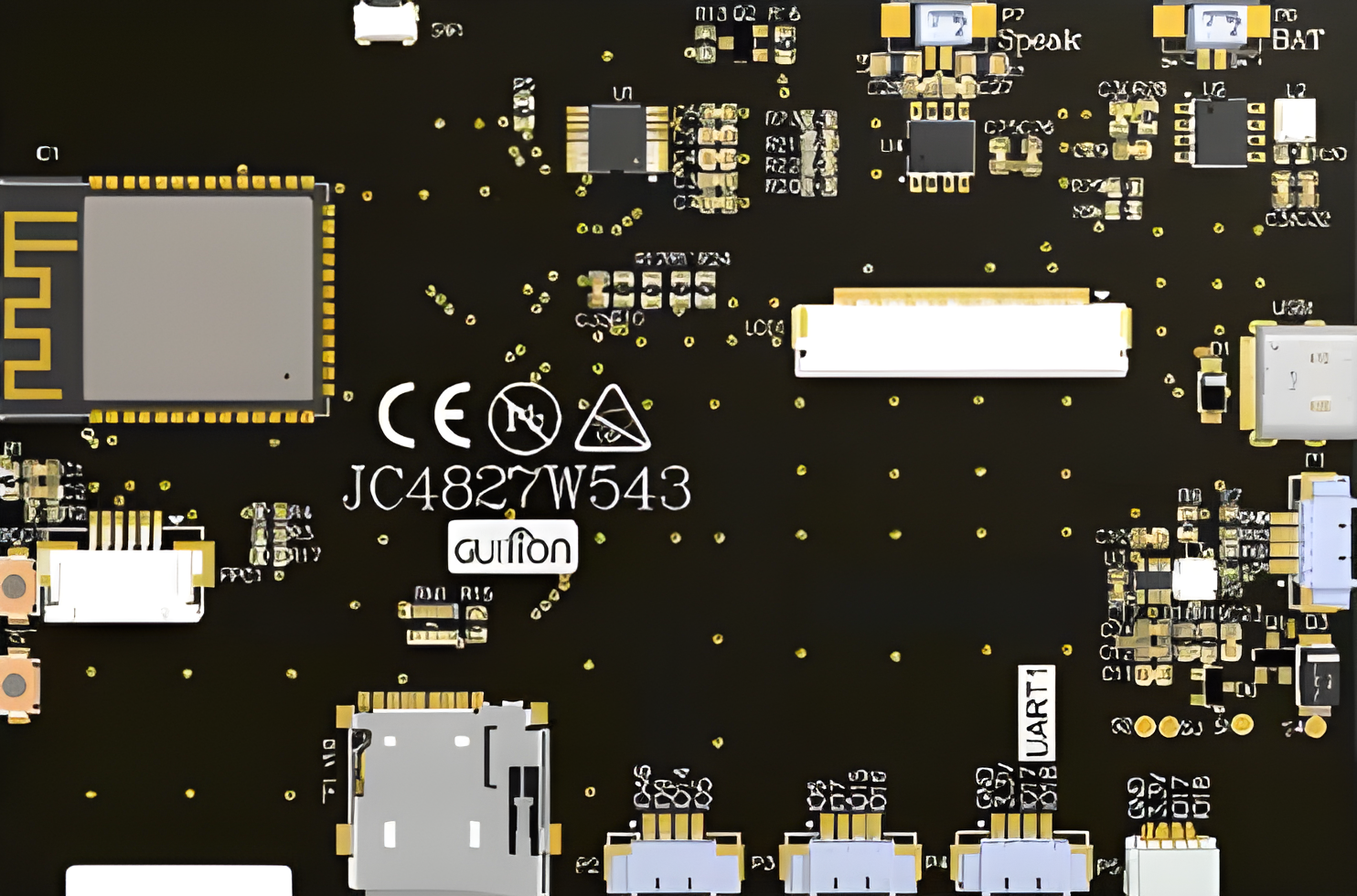
The ESP32-S3-N4R8 4.3-inch, manufactured by Guition (Part ID: JC4827W543), is a powerful microcontroller with integrated Wi-Fi and Bluetooth capabilities. It features a 4.3-inch TFT display, making it ideal for applications requiring a graphical user interface. This component is designed for IoT, smart home devices, industrial automation, and portable electronics, offering high performance and versatility.
Explore Projects Built with ESP32-S3-N4R8 4.3-inch

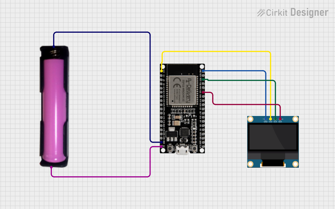
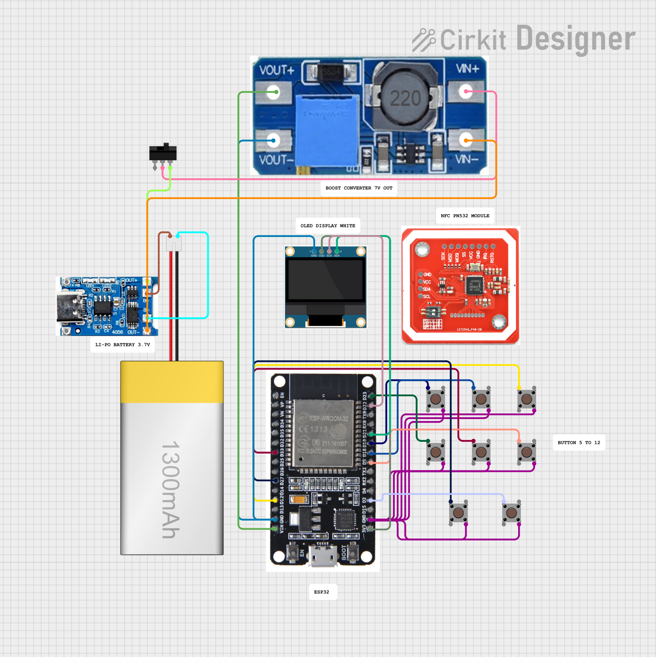

Explore Projects Built with ESP32-S3-N4R8 4.3-inch
Common Applications:
- Smart home control panels
- Industrial monitoring systems
- IoT dashboards
- Portable medical devices
- Educational and prototyping projects
Technical Specifications
Key Technical Details:
| Parameter | Value |
|---|---|
| Microcontroller | ESP32-S3 (Xtensa® 32-bit LX7 CPU) |
| Flash Memory | 8 MB |
| PSRAM | 8 MB |
| Display Size | 4.3 inches |
| Display Resolution | 480 x 272 pixels |
| Wi-Fi Standard | 802.11 b/g/n |
| Bluetooth Version | Bluetooth 5.0 (LE) |
| Operating Voltage | 3.3V |
| Power Consumption | ~240 mA (active), ~10 µA (deep sleep) |
| GPIO Pins | 34 |
| Communication Interfaces | UART, SPI, I2C, I2S, CAN, PWM |
| Operating Temperature | -40°C to 85°C |
Pin Configuration and Descriptions:
| Pin Number | Pin Name | Description |
|---|---|---|
| 1 | VCC | Power supply input (3.3V) |
| 2 | GND | Ground |
| 3 | GPIO0 | General-purpose I/O, boot mode selection |
| 4 | GPIO1 | General-purpose I/O, UART TX |
| 5 | GPIO2 | General-purpose I/O, UART RX |
| 6 | GPIO3 | General-purpose I/O, SPI MOSI |
| 7 | GPIO4 | General-purpose I/O, SPI MISO |
| 8 | GPIO5 | General-purpose I/O, SPI CLK |
| 9 | GPIO6 | General-purpose I/O, I2C SDA |
| 10 | GPIO7 | General-purpose I/O, I2C SCL |
| 11 | RESET | Reset pin |
| 12 | TOUCH1 | Capacitive touch input 1 |
| 13 | TOUCH2 | Capacitive touch input 2 |
| 14 | BACKLIGHT | Display backlight control |
| 15 | LCD_DATA0 | LCD data line 0 |
| 16 | LCD_DATA1 | LCD data line 1 |
| ... | ... | ... (Refer to the full datasheet for all pins) |
Usage Instructions
How to Use the Component in a Circuit:
- Power Supply: Connect the VCC pin to a 3.3V regulated power source and GND to ground.
- Display Connection: Use the LCD_DATA pins to interface with the 4.3-inch display. Ensure proper initialization in your code.
- Wi-Fi and Bluetooth: Configure the ESP32-S3 for wireless communication using the appropriate libraries (e.g.,
WiFi.handBluetoothSerial.h). - GPIO Usage: Use the GPIO pins for interfacing with sensors, actuators, or other peripherals.
- Touch Inputs: Connect the TOUCH pins to capacitive touch sensors for user interaction.
- Backlight Control: Use the BACKLIGHT pin to adjust the display brightness via PWM.
Important Considerations:
- Ensure the power supply is stable and within the specified voltage range (3.3V).
- Use level shifters if interfacing with 5V logic devices.
- Avoid exceeding the maximum current rating of GPIO pins (40 mA per pin).
- Properly terminate unused pins to avoid floating inputs.
- Use decoupling capacitors near the power pins for noise reduction.
Example Code for Arduino UNO:
Below is an example of initializing the ESP32-S3 with the 4.3-inch display and Wi-Fi:
#include <WiFi.h> // Include Wi-Fi library for ESP32-S3
#include <TFT_eSPI.h> // Include TFT display library

// Wi-Fi credentials
const char* ssid = "Your_SSID";
const char* password = "Your_PASSWORD";

// Initialize TFT display
TFT_eSPI tft = TFT_eSPI();

void setup() {
  // Initialize serial communication
  Serial.begin(115200);

  // Initialize TFT display
  tft.init();
  tft.setRotation(1); // Set display orientation
  tft.fillScreen(TFT_BLACK); // Clear the screen
  tft.setTextColor(TFT_WHITE);
  tft.drawString("Initializing...", 10, 10);

  // Connect to Wi-Fi
  WiFi.begin(ssid, password);
  tft.drawString("Connecting to Wi-Fi...", 10, 30);

  while (WiFi.status() != WL_CONNECTED) {
    delay(500);
    Serial.print(".");
  }

  // Display connection status
  tft.fillScreen(TFT_BLACK);
  tft.drawString("Wi-Fi Connected!", 10, 10);
  tft.drawString("IP Address: ", 10, 30);
  tft.drawString(WiFi.localIP().toString().c_str(), 10, 50);
}

void loop() {
  // Main loop can include additional functionality
}
Notes:
- Install the TFT_eSPI library and configure it for the ESP32-S3 in the
User_Setup.hfile. - Replace
Your_SSIDandYour_PASSWORDwith your Wi-Fi credentials.
Troubleshooting and FAQs
Common Issues:
Wi-Fi Connection Fails:
- Cause: Incorrect SSID or password.
- Solution: Double-check your Wi-Fi credentials and ensure the network is active.
Display Not Working:
- Cause: Incorrect wiring or initialization.
- Solution: Verify the connections to the LCD_DATA pins and ensure the display library is properly configured.
Touch Inputs Not Responding:
- Cause: Improper grounding or faulty touch sensors.
- Solution: Check the TOUCH pin connections and ensure proper grounding.
Microcontroller Overheating:
- Cause: Excessive current draw or improper power supply.
- Solution: Use a stable 3.3V power source and avoid overloading GPIO pins.
Tips for Troubleshooting:
- Use a multimeter to verify voltage levels at the VCC and GND pins.
- Check the serial monitor for error messages during debugging.
- Update the ESP32-S3 firmware and libraries to the latest versions.
FAQs:
Can I use the ESP32-S3-N4R8 with a 5V power supply?
- No, the ESP32-S3-N4R8 operates at 3.3V. Use a voltage regulator if needed.
What is the maximum resolution supported by the display?
- The 4.3-inch display supports a resolution of 480 x 272 pixels.
Can I use this component with Arduino IDE?
- Yes, the ESP32-S3 is fully compatible with the Arduino IDE. Install the ESP32 board package to get started.
Does the component support OTA updates?
- Yes, the ESP32-S3 supports Over-The-Air (OTA) updates for firmware.
By following this documentation, users can effectively integrate the ESP32-S3-N4R8 4.3-inch into their projects and troubleshoot common issues with ease.