How to Use Traffic Light (5V): Examples, Pinouts, and Specs
Introduction
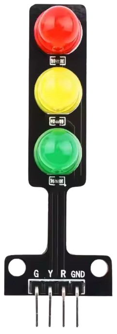
The Traffic Light (5V) is a compact electronic component designed to simulate a real-world traffic light system. It operates at a standard 5V DC supply and features three LEDs: red, yellow, and green. This component is commonly used in model railroads, educational projects, and hobbyist electronics to demonstrate traffic control systems or to add realistic lighting effects to dioramas and simulations.
Explore Projects Built with Traffic Light (5V)
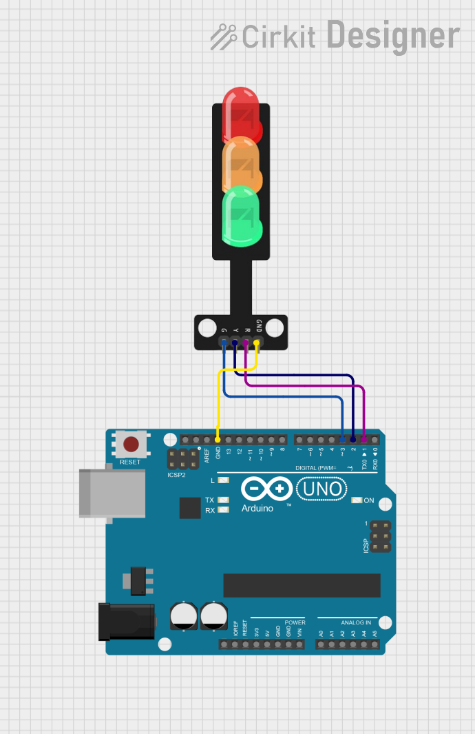
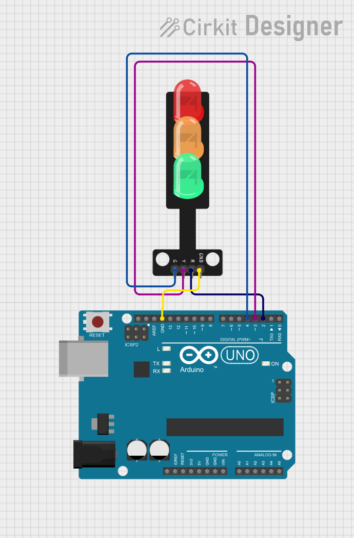
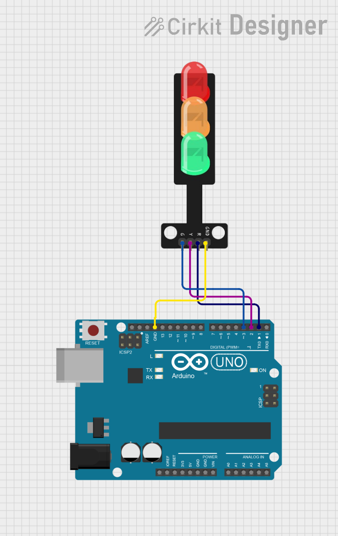
Explore Projects Built with Traffic Light (5V)
Common Applications and Use Cases
- Model railroads and miniature cityscapes
- Educational demonstrations of traffic control systems
- Arduino-based projects for learning programming and electronics
- Simulations of real-world traffic scenarios
- Decorative or functional lighting in hobbyist projects
Technical Specifications
The following table outlines the key technical details of the Traffic Light (5V):
| Parameter | Specification |
|---|---|
| Operating Voltage | 5V DC |
| Current Consumption | ~20mA per LED |
| LED Colors | Red, Yellow, Green |
| Dimensions | ~25mm x 10mm x 10mm |
| Connector Type | 3-pin or 4-pin header (varies) |
| LED Type | Diffused |
Pin Configuration and Descriptions
The Traffic Light (5V) typically comes with a 3-pin or 4-pin header for easy connection. Below is the pin configuration:
3-Pin Header Configuration
| Pin Number | Label | Description |
|---|---|---|
| 1 | GND | Ground connection |
| 2 | VCC | 5V power supply |
| 3 | Signal | Control signal for LED switching |
4-Pin Header Configuration
| Pin Number | Label | Description |
|---|---|---|
| 1 | GND | Ground connection |
| 2 | RED | Control signal for the red LED |
| 3 | YELLOW | Control signal for the yellow LED |
| 4 | GREEN | Control signal for the green LED |
Usage Instructions
How to Use the Traffic Light (5V) in a Circuit
- Power Supply: Connect the
VCCpin to a 5V DC power source and theGNDpin to ground. - Control Signals: Use a microcontroller (e.g., Arduino UNO) or a simple switch circuit to control the LEDs. For a 4-pin header, each LED can be controlled individually by applying a HIGH signal to its respective pin.
- Resistors: If not built-in, use appropriate current-limiting resistors (typically 220Ω to 330Ω) in series with each LED to prevent damage.
Important Considerations and Best Practices
- Polarity: Ensure correct polarity when connecting the component to avoid damage.
- Current Limiting: Always use resistors if the component does not have built-in current limiting.
- Signal Timing: When simulating traffic light behavior, use appropriate delays between LED transitions to mimic real-world timing.
- Testing: Test the component with a multimeter or simple circuit before integrating it into a larger project.
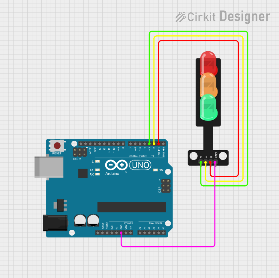
Example: Using the Traffic Light (5V) with Arduino UNO
Below is an example Arduino sketch to control the Traffic Light (5V) with a 4-pin header:
// Pin assignments for the traffic light
const int redPin = 8;     // Red LED connected to pin 8
const int yellowPin = 9;  // Yellow LED connected to pin 9
const int greenPin = 10;  // Green LED connected to pin 10

void setup() {
  // Set the LED pins as outputs
  pinMode(redPin, OUTPUT);
  pinMode(yellowPin, OUTPUT);
  pinMode(greenPin, OUTPUT);
}

void loop() {
  // Simulate traffic light sequence

  // Turn on the red light for 5 seconds
  digitalWrite(redPin, HIGH);
  delay(5000); // Wait for 5 seconds
  digitalWrite(redPin, LOW);

  // Turn on the yellow light for 2 seconds
  digitalWrite(yellowPin, HIGH);
  delay(2000); // Wait for 2 seconds
  digitalWrite(yellowPin, LOW);

  // Turn on the green light for 5 seconds
  digitalWrite(greenPin, HIGH);
  delay(5000); // Wait for 5 seconds
  digitalWrite(greenPin, LOW);
}
Troubleshooting and FAQs
Common Issues and Solutions
LEDs Not Lighting Up:
- Check the power supply and ensure it is providing 5V DC.
- Verify the connections and ensure the pins are correctly wired.
- Test the LEDs individually with a multimeter or a simple circuit.
Flickering LEDs:
- Ensure the control signals are stable and not fluctuating.
- Check for loose connections or poor soldering.
Overheating:
- Verify that current-limiting resistors are used if required.
- Ensure the component is not exposed to voltages higher than 5V.
Incorrect LED Behavior:
- Double-check the pin assignments in your code or circuit.
- Ensure the microcontroller is functioning correctly and the code logic is accurate.
FAQs
Q: Can I use the Traffic Light (5V) with a 3.3V microcontroller?
A: Yes, but the LEDs may appear dim. Use a level shifter or ensure the control signals are compatible with 5V logic.
Q: Does the Traffic Light (5V) have built-in resistors?
A: Some models include built-in resistors, but others do not. Check the product datasheet or test with a multimeter to confirm.
Q: Can I control the Traffic Light (5V) without a microcontroller?
A: Yes, you can use simple switches or a 555 timer circuit to control the LEDs manually.
Q: How do I extend the wires for a larger project?
A: Use appropriately rated wires and ensure secure connections to avoid voltage drops or signal interference.