Cirkit Designer Logo
Cirkit Designer
Your all-in-one circuit design IDE
Home / 
Component Documentation

How to Use FireBeetle OSD Character Overlay Module: Examples, Pinouts, and Specs

Image of FireBeetle OSD Character Overlay Module
Cirkit Designer LogoDesign with FireBeetle OSD Character Overlay Module in Cirkit Designer

Introduction

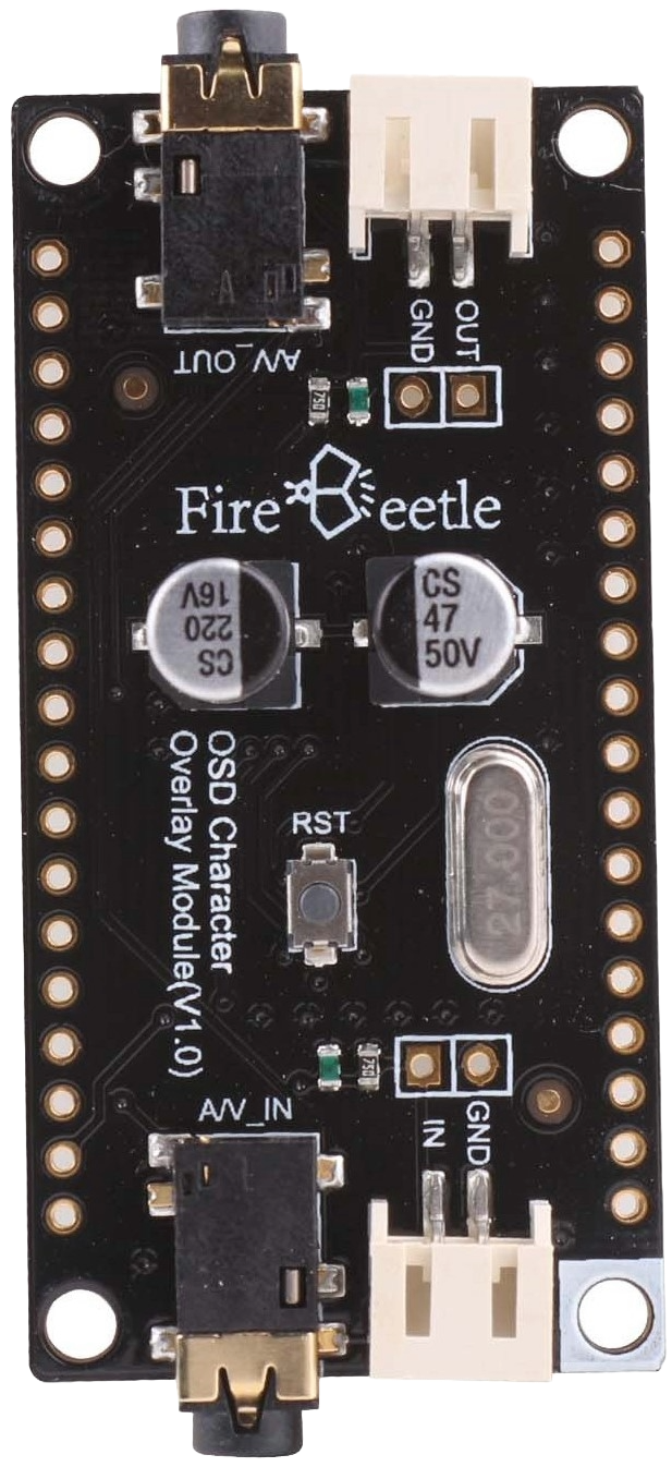
The FireBeetle OSD (On-Screen Display) Character Overlay Module by DFRobot is an electronic component designed to overlay text and graphical information onto video signals. This module is commonly used in applications such as FPV (First Person View) systems for drones, video monitoring, and any system requiring real-time information display over video feeds.

Explore Projects Built with FireBeetle OSD Character Overlay Module

Use Cirkit Designer to design, explore, and prototype these projects online. Some projects support real-time simulation. Click "Open Project" to start designing instantly!
Arduino UNO OLED Display and Buzzer Melody Project
Image of ardunio_uno_buzzer_happy_oled: A project utilizing FireBeetle OSD Character Overlay Module in a practical application
This circuit features an Arduino UNO microcontroller that drives a 0.96" OLED display and a buzzer module. The OLED display shows a bitmap image, while the buzzer plays a melody upon initialization.
Cirkit Designer LogoOpen Project in Cirkit Designer
ESP32-Based Smart Fire and Gas Detection System with GSM and OLED Display
Image of outline robotics: A project utilizing FireBeetle OSD Character Overlay Module in a practical application
This circuit is a multi-sensor monitoring system using an ESP32 microcontroller. It integrates various sensors including flame sensors, gas sensors (MQ-2 and MQ-7), a temperature and humidity sensor, and an OLED display for real-time data visualization. Additionally, it includes a relay module for controlling external devices and a GSM module for remote communication.
Cirkit Designer LogoOpen Project in Cirkit Designer
ESP32-Based Smart Display with OLED, LED, and Buzzer
Image of EXP2: A project utilizing FireBeetle OSD Character Overlay Module in a practical application
This circuit features an ESP32 microcontroller that drives a 0.96" OLED display, a red LED, and a piezo buzzer. The ESP32 displays scrolling text and a bitmap on the OLED, controls the LED, and generates a tone on the buzzer, providing a simple interactive display and alert system.
Cirkit Designer LogoOpen Project in Cirkit Designer
ESP32-Based CO Sensor with OLED Display
Image of ESP32-ME2-CO: A project utilizing FireBeetle OSD Character Overlay Module in a practical application
This circuit features an ESP32 microcontroller interfaced with a 0.96" OLED display and an ME2-CO carbon monoxide sensor. The ESP32 reads data from the CO sensor and displays the information on the OLED screen, providing a compact solution for monitoring CO levels.
Cirkit Designer LogoOpen Project in Cirkit Designer

Explore Projects Built with FireBeetle OSD Character Overlay Module

Use Cirkit Designer to design, explore, and prototype these projects online. Some projects support real-time simulation. Click "Open Project" to start designing instantly!
Image of ardunio_uno_buzzer_happy_oled: A project utilizing FireBeetle OSD Character Overlay Module in a practical application
Arduino UNO OLED Display and Buzzer Melody Project
This circuit features an Arduino UNO microcontroller that drives a 0.96" OLED display and a buzzer module. The OLED display shows a bitmap image, while the buzzer plays a melody upon initialization.
Cirkit Designer LogoOpen Project in Cirkit Designer
Image of outline robotics: A project utilizing FireBeetle OSD Character Overlay Module in a practical application
ESP32-Based Smart Fire and Gas Detection System with GSM and OLED Display
This circuit is a multi-sensor monitoring system using an ESP32 microcontroller. It integrates various sensors including flame sensors, gas sensors (MQ-2 and MQ-7), a temperature and humidity sensor, and an OLED display for real-time data visualization. Additionally, it includes a relay module for controlling external devices and a GSM module for remote communication.
Cirkit Designer LogoOpen Project in Cirkit Designer
Image of EXP2: A project utilizing FireBeetle OSD Character Overlay Module in a practical application
ESP32-Based Smart Display with OLED, LED, and Buzzer
This circuit features an ESP32 microcontroller that drives a 0.96" OLED display, a red LED, and a piezo buzzer. The ESP32 displays scrolling text and a bitmap on the OLED, controls the LED, and generates a tone on the buzzer, providing a simple interactive display and alert system.
Cirkit Designer LogoOpen Project in Cirkit Designer
Image of ESP32-ME2-CO: A project utilizing FireBeetle OSD Character Overlay Module in a practical application
ESP32-Based CO Sensor with OLED Display
This circuit features an ESP32 microcontroller interfaced with a 0.96" OLED display and an ME2-CO carbon monoxide sensor. The ESP32 reads data from the CO sensor and displays the information on the OLED screen, providing a compact solution for monitoring CO levels.
Cirkit Designer LogoOpen Project in Cirkit Designer

Common Applications and Use Cases

  • FPV systems for drones and remote-controlled vehicles
  • Video monitoring systems
  • Amateur television (ATV)
  • Custom video display systems

Technical Specifications

The FireBeetle OSD Character Overlay Module is designed to be lightweight and easy to integrate into existing video systems. Below are the key technical specifications:

Specification Detail
Operating Voltage 3.3V - 5V
Video Standard NTSC/PAL
Communication SPI Interface
Operating Current 15mA (Typical)
Character Color Configurable (White, Black, Inverted, etc.)
Background Color Configurable (Transparent, Black, etc.)
Dimensions 27mm x 27mm

Pin Configuration and Descriptions

Pin Number Name Description
1 VCC Power supply (3.3V - 5V)
2 GND Ground
3 CS Chip Select for SPI communication
4 MOSI Master Out Slave In for SPI communication
5 SCK Serial Clock for SPI communication
6 RX Video signal input
7 TX Video signal output with OSD

Usage Instructions

Integrating with a Circuit

  1. Power Supply: Connect the VCC pin to a 3.3V or 5V power source and the GND pin to the common ground.
  2. Video Signal: Connect the video source to the RX pin and the display device to the TX pin.
  3. SPI Communication: Connect the CS, MOSI, and SCK pins to the corresponding SPI pins on the microcontroller (e.g., Arduino).

Important Considerations and Best Practices

  • Ensure that the power supply is within the specified voltage range to prevent damage.
  • Use a level shifter if the microcontroller operates at a different logic level than the module.
  • Keep the video signal cables as short as possible to minimize signal degradation.
  • Avoid placing the module near high-frequency devices to prevent electromagnetic interference.

Example Code for Arduino UNO

#include <SPI.h>

// Define the SPI pins for Arduino UNO
#define CS_PIN 10

void setup() {
  // Initialize SPI communication
  SPI.begin();
  pinMode(CS_PIN, OUTPUT);
  digitalWrite(CS_PIN, HIGH); // Deselect the module
}

void loop() {
  // Example function to send data to the OSD module
  sendOSDData("Hello, World!");
}

void sendOSDData(const char* str) {
  // Select the OSD module
  digitalWrite(CS_PIN, LOW);
  
  // Send each character of the string
  for (unsigned int i = 0; i < strlen(str); i++) {
    SPI.transfer((byte)str[i]);
  }
  
  // Deselect the OSD module
  digitalWrite(CS_PIN, HIGH);
}

Troubleshooting and FAQs

Common Issues

  • No OSD on the Video Output: Check the connections to the RX and TX pins and ensure the video source is functioning.
  • Garbled Characters: Ensure that the SPI communication is correctly set up and that the correct voltage levels are used.
  • Intermittent OSD: Check for loose connections and ensure that the power supply is stable.

Solutions and Tips for Troubleshooting

  • Double-check all connections, especially the SPI lines and power supply.
  • Use a multimeter to verify the voltage levels at the VCC and GND pins.
  • If using long cables, consider using shielded cables to reduce noise.
  • Ensure that the microcontroller's SPI library is correctly configured for the module.

FAQs

Q: Can the module be used with both NTSC and PAL video standards? A: Yes, the module supports both NTSC and PAL standards.

Q: Is it possible to change the text color and background? A: Yes, the module allows configuration of character and background colors.

Q: What is the maximum length for the overlay text? A: The maximum length depends on the screen resolution and character size. It's important to manage the screen space efficiently.

Q: Can I use this module with other microcontrollers besides Arduino? A: Yes, as long as the microcontroller supports SPI communication and operates within the voltage range of the module.