How to Use GY-BNO055: Examples, Pinouts, and Specs
Introduction
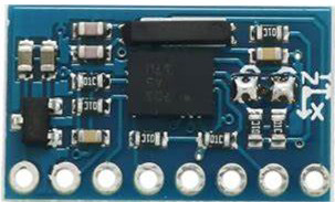
The GY-BNO055 is a 9-axis sensor module that integrates a gyroscope, accelerometer, and magnetometer into a single package. Unlike traditional sensor modules, the GY-BNO055 features an onboard microcontroller that performs sensor fusion, providing orientation data directly in the form of Euler angles or quaternions. This eliminates the need for complex calculations on the host microcontroller, making it an ideal choice for applications requiring precise motion tracking and orientation sensing.
Explore Projects Built with GY-BNO055


Explore Projects Built with GY-BNO055
Common Applications
- Robotics and autonomous vehicles
- Virtual reality (VR) and augmented reality (AR) systems
- Drone stabilization and navigation
- Wearable devices for motion tracking
- Industrial automation and control systems
Technical Specifications
The GY-BNO055 module is designed for ease of use and high performance. Below are its key technical details:
General Specifications
| Parameter | Value |
|---|---|
| Operating Voltage | 3.3V to 5V |
| Communication Protocols | I2C, UART |
| Gyroscope Range | ±125°/s, ±250°/s, ±500°/s, |
| ±1000°/s, ±2000°/s | |
| Accelerometer Range | ±2g, ±4g, ±8g, ±16g |
| Magnetometer Range | ±1300 µT |
| Output Data | Euler angles, quaternions, |
| linear acceleration, gravity | |
| Operating Temperature | -40°C to +85°C |
| Dimensions | 21mm x 16mm x 3.8mm |
Pin Configuration
The GY-BNO055 module has a standard pinout for easy integration into circuits. Below is the pin configuration:
| Pin Name | Description |
|---|---|
| VIN | Power input (3.3V to 5V) |
| GND | Ground |
| SDA | I2C data line |
| SCL | I2C clock line |
| PS0 | Protocol selection (I2C or UART) |
| PS1 | Protocol selection (I2C or UART) |
| RST | Reset pin (active low) |
| INT | Interrupt pin (optional, for advanced use) |
Usage Instructions
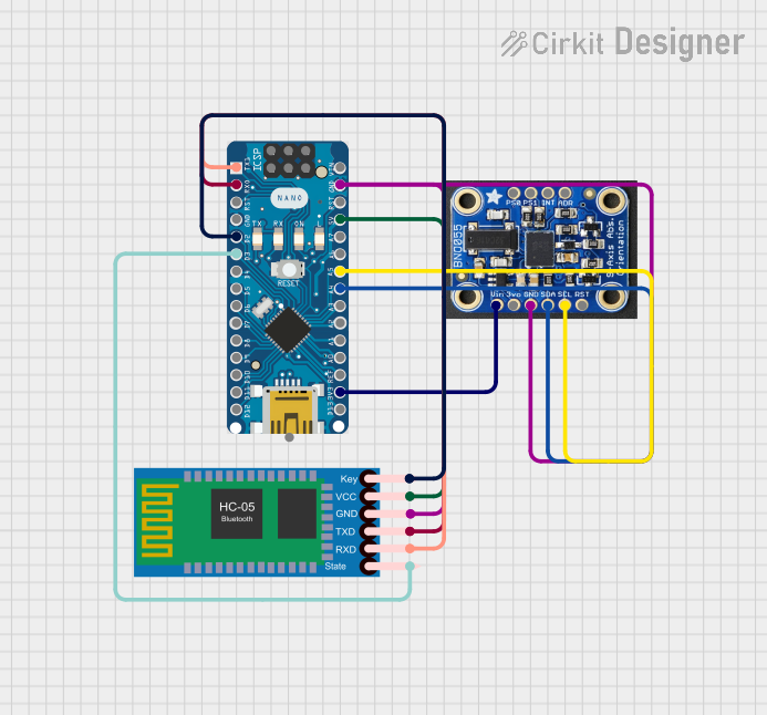
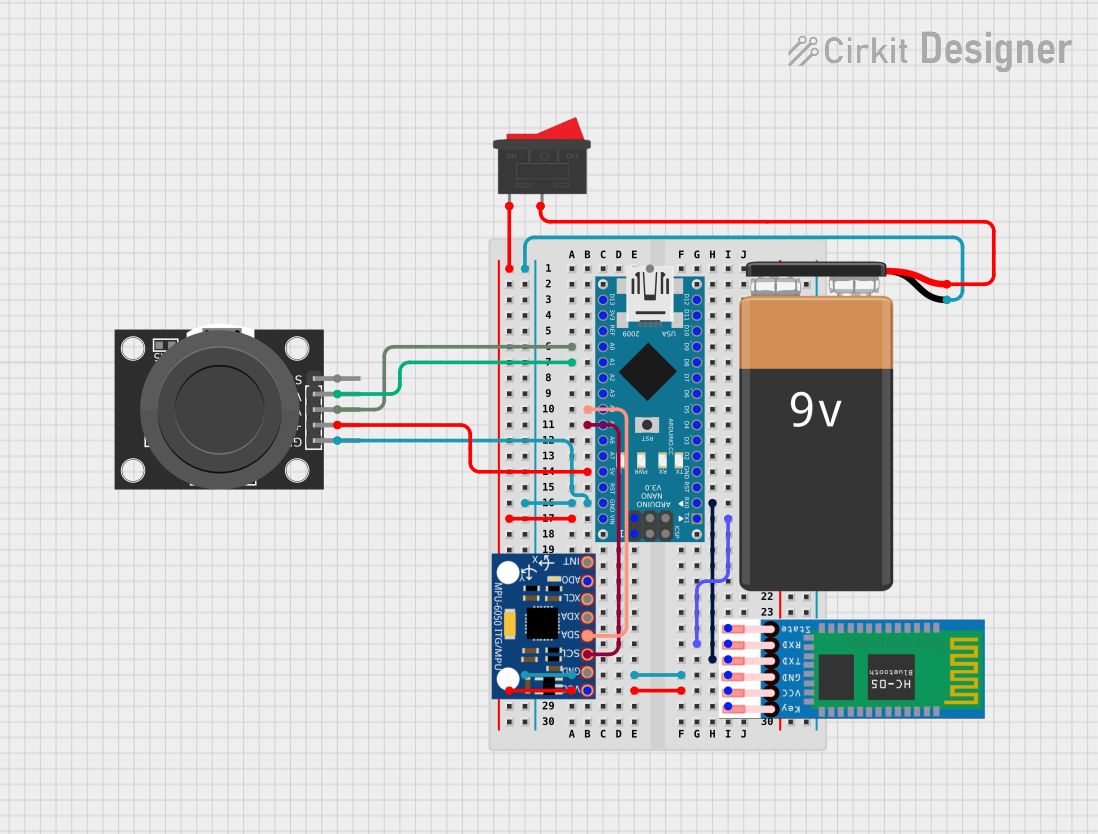
Connecting the GY-BNO055 to an Arduino UNO
The GY-BNO055 can be easily connected to an Arduino UNO using the I2C protocol. Below is a step-by-step guide:
Wiring:
- Connect the
VINpin of the GY-BNO055 to the 5V pin on the Arduino. - Connect the
GNDpin of the GY-BNO055 to the GND pin on the Arduino. - Connect the
SDApin of the GY-BNO055 to the A4 pin on the Arduino. - Connect the
SCLpin of the GY-BNO055 to the A5 pin on the Arduino.
- Connect the
Install Required Libraries:
- Install the "Adafruit BNO055" library from the Arduino Library Manager.
Example Code: Use the following code to read orientation data from the GY-BNO055:
#include <Wire.h>
#include <Adafruit_Sensor.h>
#include <Adafruit_BNO055.h>

// Create an instance of the BNO055 sensor
Adafruit_BNO055 bno = Adafruit_BNO055(55);

void setup() {
  Serial.begin(9600);
  // Initialize the BNO055 sensor
  if (!bno.begin()) {
    Serial.println("Error: BNO055 not detected. Check wiring or I2C address.");
    while (1);
  }
  Serial.println("BNO055 initialized successfully!");
  bno.setExtCrystalUse(true); // Use external crystal for better accuracy
}

void loop() {
  // Get Euler angles (heading, roll, pitch)
  sensors_event_t event;
  bno.getEvent(&event);

  Serial.print("Heading: ");
  Serial.print(event.orientation.x);
  Serial.print("°, Roll: ");
  Serial.print(event.orientation.y);
  Serial.print("°, Pitch: ");
  Serial.print(event.orientation.z);
  Serial.println("°");

  delay(500); // Delay for readability
}
Important Considerations
- Power Supply: Ensure the module is powered within its operating voltage range (3.3V to 5V). Exceeding this range may damage the module.
- I2C Address: The default I2C address of the GY-BNO055 is
0x28. If theADRpin is pulled high, the address changes to0x29. - Protocol Selection: Use the
PS0andPS1pins to select between I2C and UART communication. For I2C, both pins should be set to low (default configuration). - External Crystal: Enabling the external crystal oscillator improves accuracy and stability.
Troubleshooting and FAQs
Common Issues
Sensor Not Detected:
- Cause: Incorrect wiring or I2C address mismatch.
- Solution: Double-check the connections and ensure the correct I2C address is used in the code.
Inaccurate Orientation Data:
- Cause: Sensor not calibrated.
- Solution: Perform calibration by following the Adafruit BNO055 library's calibration example. Move the sensor in all directions to complete the process.
No Output on Serial Monitor:
- Cause: Incorrect baud rate or serial monitor settings.
- Solution: Ensure the serial monitor is set to 9600 baud.
Random Freezing or Resetting:
- Cause: Insufficient power supply or electrical noise.
- Solution: Use a decoupling capacitor (e.g., 0.1µF) near the module's power pins.
FAQs
Can the GY-BNO055 be used with 3.3V microcontrollers?
- Yes, the module is compatible with both 3.3V and 5V systems.
What is the maximum update rate of the sensor?
- The GY-BNO055 can provide data at up to 100Hz.
How do I reset the sensor?
- Pull the
RSTpin low for at least 1ms to reset the module.
- Pull the
Can I use the GY-BNO055 with UART instead of I2C?
- Yes, configure the
PS0andPS1pins for UART mode and connect theTXandRXpins accordingly.
- Yes, configure the
By following this documentation, you can effectively integrate the GY-BNO055 into your projects and troubleshoot common issues with ease.