How to Use Adafruit TB6612 DC and Stepper Motor Driver: Examples, Pinouts, and Specs
Introduction
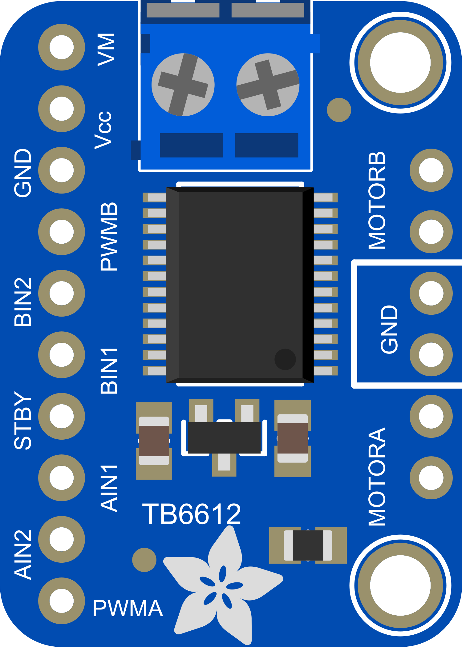
The Adafruit TB6612 DC and Stepper Motor Driver is a versatile and efficient motor driver designed for controlling both DC and stepper motors. It utilizes a dual-channel H-bridge configuration, allowing for independent control of two motors. This driver is ideal for projects requiring precise motor control, such as robotics, automated machinery, and custom vehicles. Its compatibility with microcontrollers like the Arduino UNO makes it a popular choice for hobbyists and educators alike.
Explore Projects Built with Adafruit TB6612 DC and Stepper Motor Driver

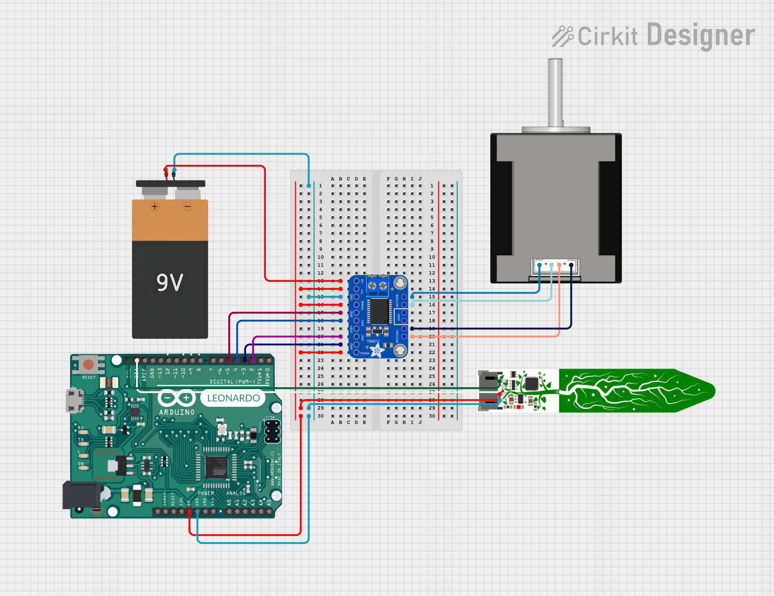
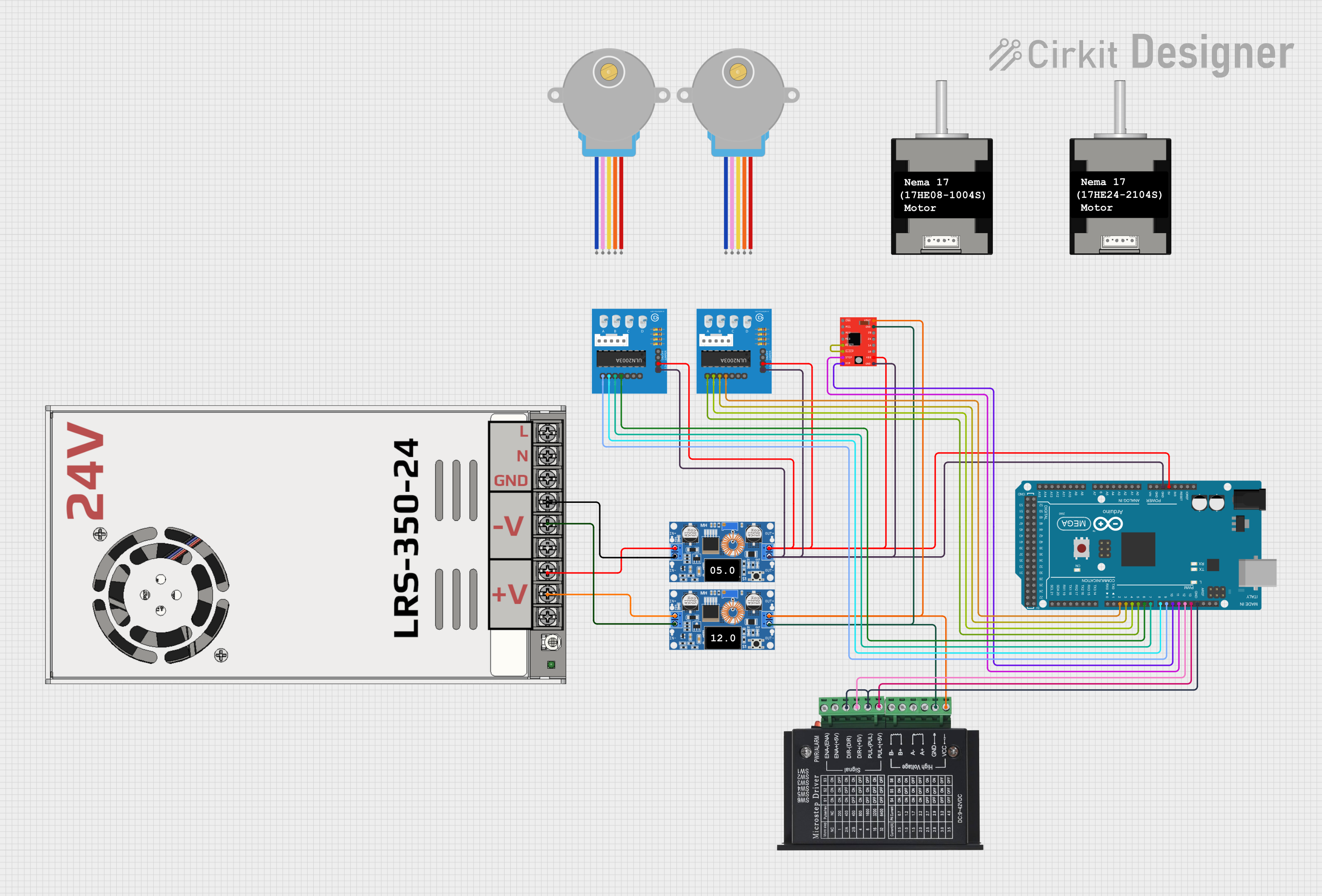
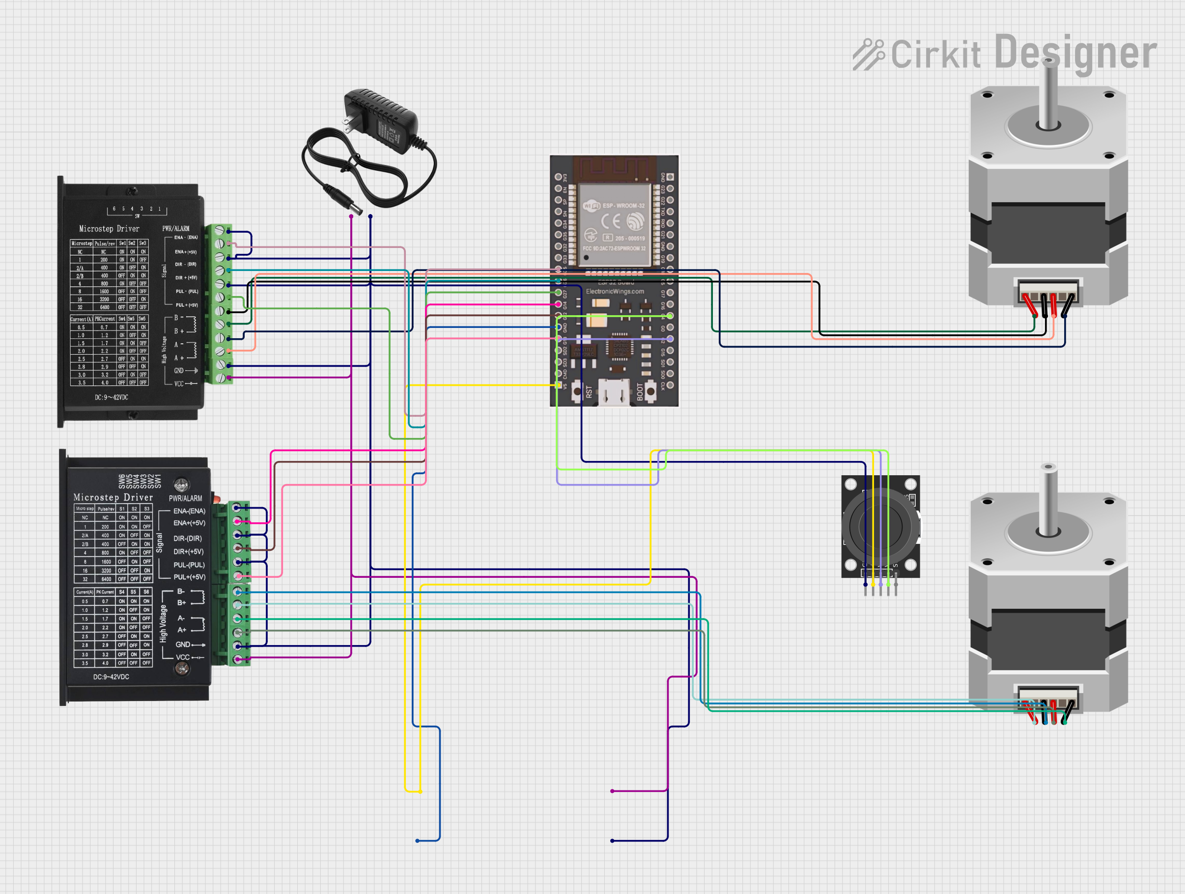
Explore Projects Built with Adafruit TB6612 DC and Stepper Motor Driver
Common Applications and Use Cases
- Robotics: Driving wheels or actuator motors.
- CNC machines: Controlling stepper motors for precise movements.
- Educational projects: Teaching motor control principles.
- DIY projects: Custom vehicles, animatronics, and more.
Technical Specifications
Key Technical Details
- Motor Voltage (VMOT): 4.5V to 13.5V
- Logic Voltage (VCC): 2.7V to 5.5V
- Output Current: 1.2A per channel (peak 3.2A)
- Standby Control to save power
Pin Configuration and Descriptions
| Pin Number | Name | Description |
|---|---|---|
| 1 | VMOT | Motor power supply (4.5V to 13.5V) |
| 2 | GND | Ground connection |
| 3 | A01 | Motor A output 1 |
| 4 | A02 | Motor A output 2 |
| 5 | B01 | Motor B output 1 |
| 6 | B02 | Motor B output 2 |
| 7 | VCC | Logic power supply (2.7V to 5.5V) |
| 8 | STBY | Standby control (active high) |
| 9 | PWMA | PWM input for motor A |
| 10 | AIN2 | Direction control for motor A |
| 11 | AIN1 | Direction control for motor A |
| 12 | BIN1 | Direction control for motor B |
| 13 | BIN2 | Direction control for motor B |
| 14 | PWMB | PWM input for motor B |
Usage Instructions
How to Use the Component in a Circuit
Power Connections:
- Connect VMOT to your motor power supply (4.5V to 13.5V).
- Connect VCC to your logic power supply (2.7V to 5.5V).
- Connect GND to the common ground of your power supplies and microcontroller.
Motor Connections:
- Connect your motor leads to A01 and A02 for motor A, and B01 and B02 for motor B.
Control Connections:
- Connect STBY to a digital pin on your microcontroller to enable or disable the driver.
- Connect PWMA and PWMB to PWM-capable digital pins for speed control.
- Connect AIN1, AIN2, BIN1, and BIN2 to digital pins for direction control.
Important Considerations and Best Practices
- Ensure that the power supply can handle the current requirements of your motors.
- Use PWM signals for speed control to maintain torque at lower speeds.
- Always set STBY to high to enable the motor driver.
- Use flyback diodes if driving inductive loads to protect against voltage spikes.
Example Code for Arduino UNO
#include <Arduino.h>

// Define the control pins
#define STBY 10
#define PWMA 9
#define AIN1 8
#define AIN2 7
#define PWMB 6
#define BIN1 5
#define BIN2 4

void setup() {
  // Set all the motor control pins to outputs
  pinMode(STBY, OUTPUT);
  pinMode(PWMA, OUTPUT);
  pinMode(AIN1, OUTPUT);
  pinMode(AIN2, OUTPUT);
  pinMode(PWMB, OUTPUT);
  pinMode(BIN1, OUTPUT);
  pinMode(BIN2, OUTPUT);

  // Take the motor driver out of standby
  digitalWrite(STBY, HIGH);
}

void loop() {
  // Drive motor A forward at full speed
  analogWrite(PWMA, 255); // Full speed
  digitalWrite(AIN1, HIGH);
  digitalWrite(AIN2, LOW);

  // Drive motor B backward at half speed
  analogWrite(PWMB, 128); // Half speed
  digitalWrite(BIN1, LOW);
  digitalWrite(BIN2, HIGH);

  delay(2000); // Run for 2 seconds

  // Stop both motors
  digitalWrite(STBY, LOW); // Put the driver in standby mode
  delay(1000); // Wait for 1 second
}
Troubleshooting and FAQs
Common Issues Users Might Face
- Motor not running: Check power supply connections, ensure STBY is set to high, and verify that the PWM and direction pins are correctly configured.
- Motor running weakly: Ensure the power supply can deliver sufficient current, and check for any loose connections.
- Overheating: This can occur if the motor is stalled or the current exceeds the rating. Make sure the motor is free to turn and that the current is within safe limits.
Solutions and Tips for Troubleshooting
- Use a multimeter to check for proper voltage levels at the power supply and across the motor driver.
- Ensure that the logic voltage (VCC) and motor voltage (VMOT) are within specified ranges.
- If using PWM for speed control, verify that the PWM frequency is within the acceptable range for the motor.
FAQs
Q: Can I drive two stepper motors with this driver? A: Yes, you can control two stepper motors by properly configuring the direction and step inputs for each motor.
Q: What should I do if the motor driver gets hot? A: Check the current draw of the motors and ensure it's within the limit. Add a heat sink or improve airflow if necessary.
Q: Can I use this motor driver with a Raspberry Pi or other microcontrollers? A: Yes, as long as the logic voltage is compatible and you can provide PWM signals, you can use this driver with various microcontrollers.