How to Use Turbidity Sensor V1.0: Examples, Pinouts, and Specs
Introduction
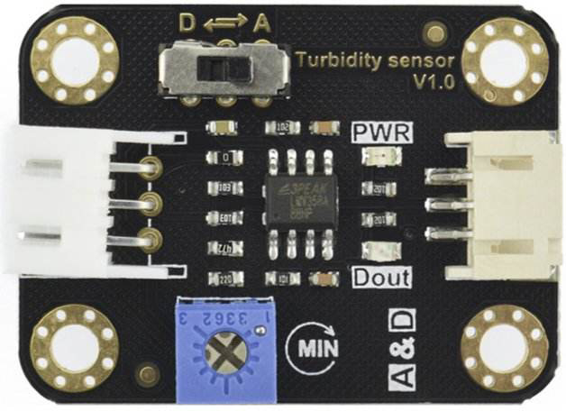
The Turbidity Sensor V1.0 by DFRobot (Part ID: Turbidity Sensor) is a device designed to measure the cloudiness or haziness of a liquid, typically water. It operates by detecting the amount of light scattered by suspended particles in the liquid. This sensor is widely used in water quality monitoring, environmental testing, and industrial applications where the clarity of a liquid is a critical parameter.
Explore Projects Built with Turbidity Sensor V1.0
Explore Projects Built with Turbidity Sensor V1.0
Common Applications and Use Cases
- Water Quality Monitoring: Assessing the cleanliness of drinking water or natural water sources.
- Environmental Testing: Measuring turbidity in rivers, lakes, and oceans to monitor pollution levels.
- Industrial Applications: Monitoring liquid clarity in food processing, beverage production, and wastewater treatment.
- Aquarium Maintenance: Ensuring optimal water conditions for aquatic life.
Technical Specifications
The following table outlines the key technical details of the Turbidity Sensor V1.0:
| Parameter | Specification |
|---|---|
| Operating Voltage | 5V DC |
| Operating Current | 40mA (typical) |
| Output Signal | Analog Voltage (0-4.5V) |
| Measurement Range | 0 NTU (clear) to 1000 NTU (cloudy) |
| Response Time | < 500ms |
| Operating Temperature | -30°C to 80°C |
| Storage Temperature | -10°C to 80°C |
| Cable Length | 20cm |
| Sensor Dimensions | 60mm x 30mm x 20mm |
Pin Configuration and Descriptions
The Turbidity Sensor V1.0 has a 3-pin interface. The pinout is as follows:
| Pin | Name | Description |
|---|---|---|
| 1 | VCC | Power supply input (5V DC) |
| 2 | GND | Ground connection |
| 3 | AOUT | Analog output signal proportional to turbidity level |
Usage Instructions
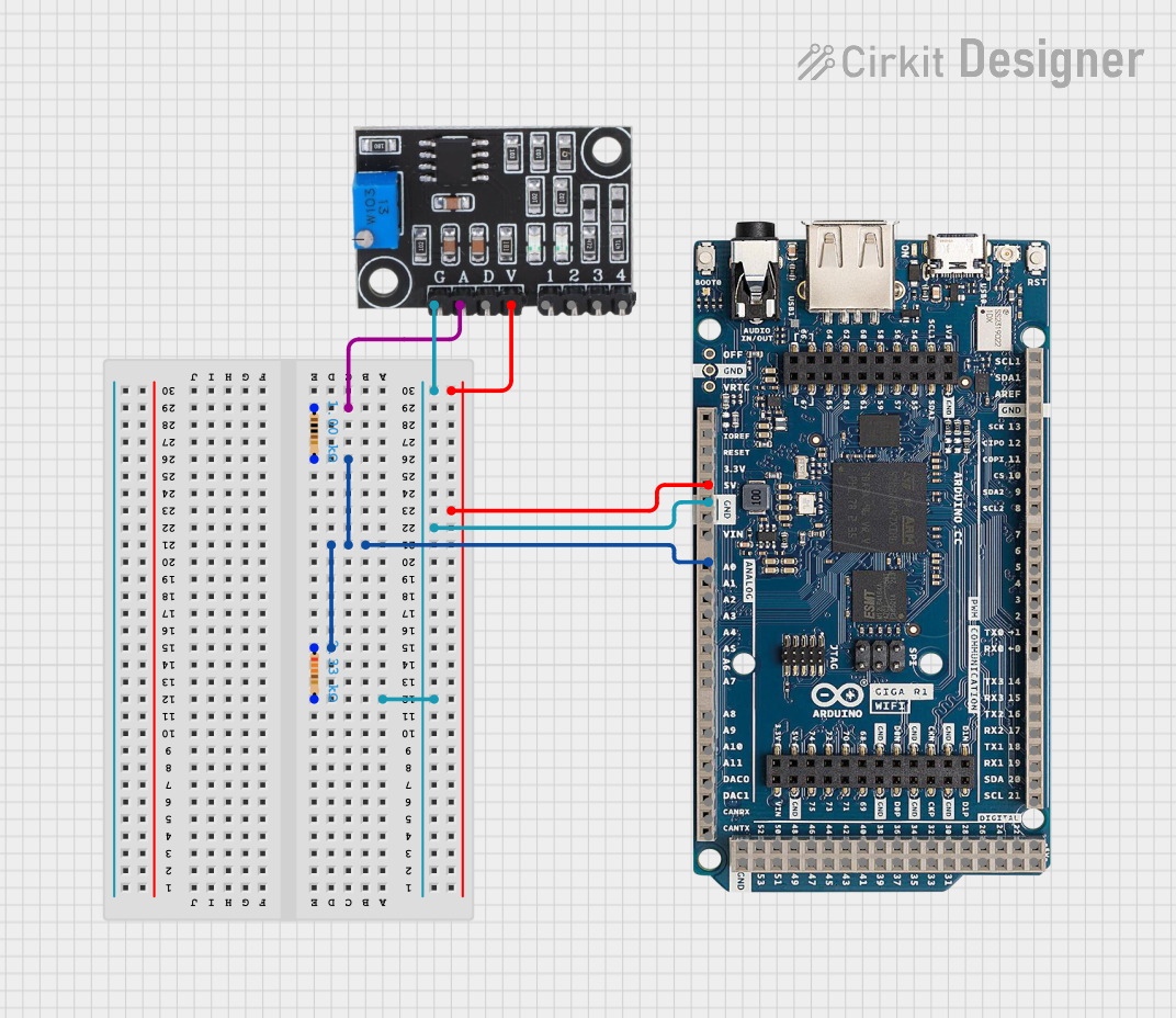
How to Use the Component in a Circuit
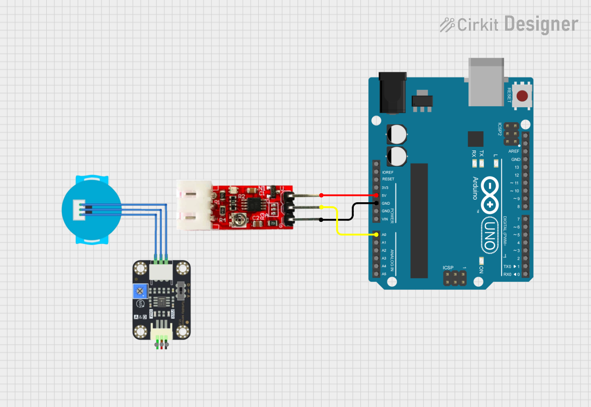
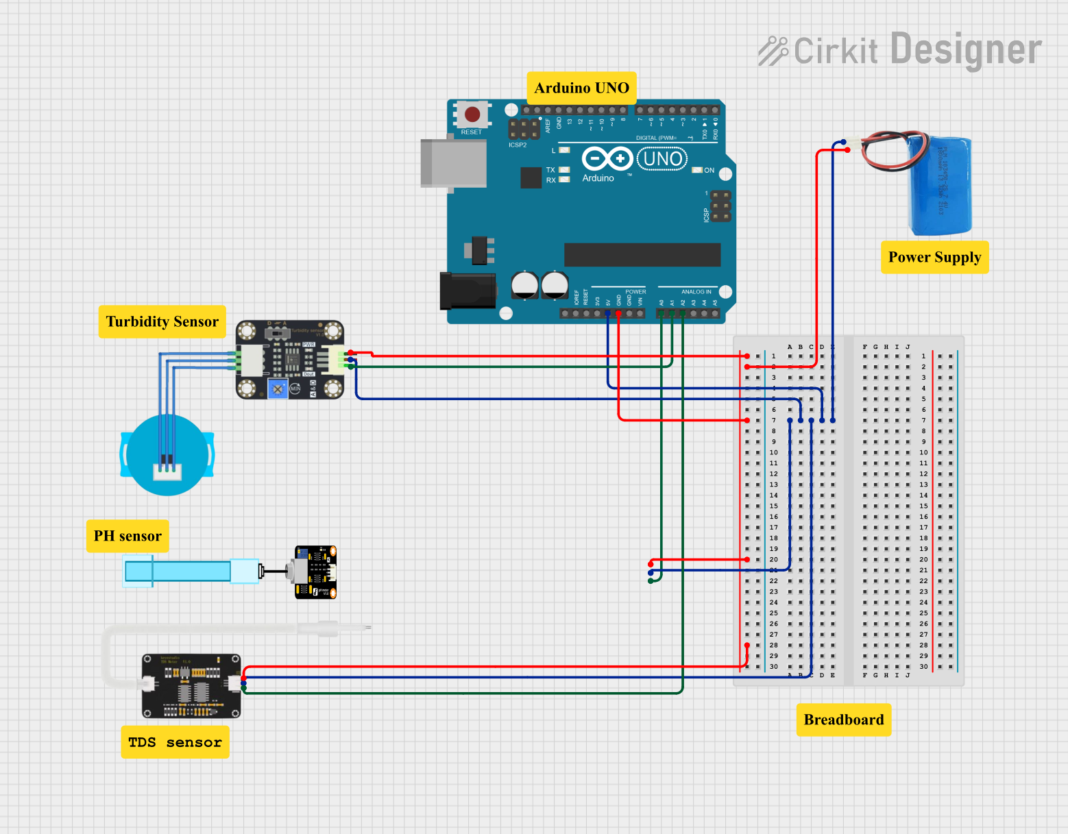
- Power the Sensor: Connect the VCC pin to a 5V DC power source and the GND pin to ground.
- Read the Output: Connect the AOUT pin to an analog input pin of a microcontroller (e.g., Arduino UNO) to read the voltage signal.
- Calibrate the Sensor: Use a clear liquid (0 NTU) and a known turbid liquid to establish a reference for your measurements.
- Interpret the Output: The analog voltage output corresponds to the turbidity level. Higher voltages indicate higher turbidity.
Important Considerations and Best Practices
- Avoid Air Bubbles: Ensure the sensor is fully submerged in the liquid without air bubbles, as they can affect the accuracy of the readings.
- Clean the Sensor Regularly: Deposits or dirt on the sensor surface can interfere with light transmission and scattering.
- Use in Stable Conditions: Minimize vibrations or rapid movements of the liquid to ensure consistent readings.
- Temperature Compensation: If used in environments with varying temperatures, consider implementing temperature compensation in your calculations.
Example Code for Arduino UNO
Below is an example of how to interface the Turbidity Sensor V1.0 with an Arduino UNO:
// Turbidity Sensor V1.0 Example Code
// This code reads the analog output of the turbidity sensor and prints the
// corresponding voltage to the Serial Monitor.

const int sensorPin = A0; // Connect the AOUT pin of the sensor to Arduino A0

void setup() {
  Serial.begin(9600); // Initialize serial communication at 9600 baud
  pinMode(sensorPin, INPUT); // Set the sensor pin as input
}

void loop() {
  int sensorValue = analogRead(sensorPin); // Read the analog value from the sensor
  float voltage = sensorValue * (5.0 / 1023.0); // Convert the value to voltage

  // Print the voltage to the Serial Monitor
  Serial.print("Turbidity Sensor Voltage: ");
  Serial.print(voltage);
  Serial.println(" V");

  delay(1000); // Wait for 1 second before the next reading
}
Troubleshooting and FAQs
Common Issues and Solutions
No Output Signal:
- Cause: Incorrect wiring or loose connections.
- Solution: Double-check the wiring and ensure all connections are secure.
Inconsistent Readings:
- Cause: Air bubbles or debris on the sensor surface.
- Solution: Submerge the sensor fully and clean it regularly.
Output Voltage Stuck at Maximum or Minimum:
- Cause: Sensor malfunction or extreme turbidity levels beyond the sensor's range.
- Solution: Verify the sensor's condition and ensure the liquid's turbidity is within the measurable range.
Sensor Not Responding to Changes in Turbidity:
- Cause: Calibration not performed or incorrect reference values.
- Solution: Recalibrate the sensor using a clear liquid and a known turbid liquid.
FAQs
Q1: Can the sensor be used with liquids other than water?
A1: Yes, the sensor can measure turbidity in other transparent liquids, but calibration may be required for accurate results.
Q2: What is the lifespan of the sensor?
A2: The sensor is durable and designed for long-term use, but regular maintenance (e.g., cleaning) is essential to ensure accuracy.
Q3: Can the sensor be used underwater for extended periods?
A3: The sensor is water-resistant but not fully waterproof. Prolonged submersion may damage the sensor. Use appropriate enclosures for underwater applications.
Q4: How do I convert the voltage output to NTU?
A4: The relationship between voltage and NTU is non-linear. Refer to the sensor's datasheet for a calibration curve or perform your own calibration using known NTU standards.