Cirkit Designer Logo
Cirkit Designer
Your all-in-one circuit design IDE
Home / 
Component Documentation

How to Use VL53L0X Flight Time Sensor: Examples, Pinouts, and Specs
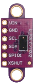

Image of VL53L0X Flight Time Sensor
Cirkit Designer LogoDesign with VL53L0X Flight Time Sensor in Cirkit Designer

Introduction

The VL53L0X is a time-of-flight (ToF) distance sensor that utilizes laser technology to measure distances with high precision. It can measure distances up to 2 meters and operates using I2C communication, making it easy to integrate into microcontroller-based systems. Its compact size and low power consumption make it ideal for applications such as robotics, drones, obstacle detection, and proximity sensing.

Explore Projects Built with VL53L0X Flight Time Sensor
Use Cirkit Designer to design, explore, and prototype these projects online. Some projects support real-time simulation. Click "Open Project" to start designing instantly!
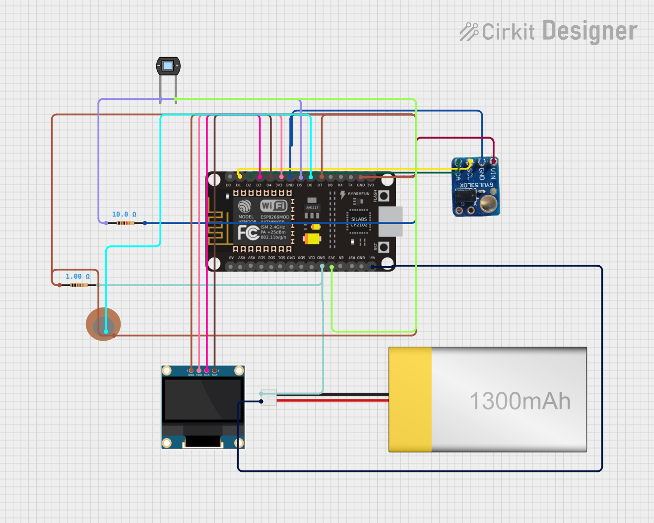
ESP8266 NodeMCU-Based Smart Eye Pressure Monitor with OLED Display and Wi-Fi Connectivity
Image of Copy of test 2 (7): A project utilizing VL53L0X Flight Time Sensor in a practical application
This circuit features an ESP8266 NodeMCU microcontroller interfaced with a VL53L0X time-of-flight distance sensor, a 0.96" OLED display, a piezo sensor, and a photodiode for light detection. The ESP8266 collects data from the sensors, displays readings on the OLED, and hosts a web server to present the information. It is likely designed for distance measurement, light intensity detection, and pressure sensing, with the capability to monitor and display these parameters in real-time over WiFi.
Cirkit Designer LogoOpen Project in Cirkit Designer
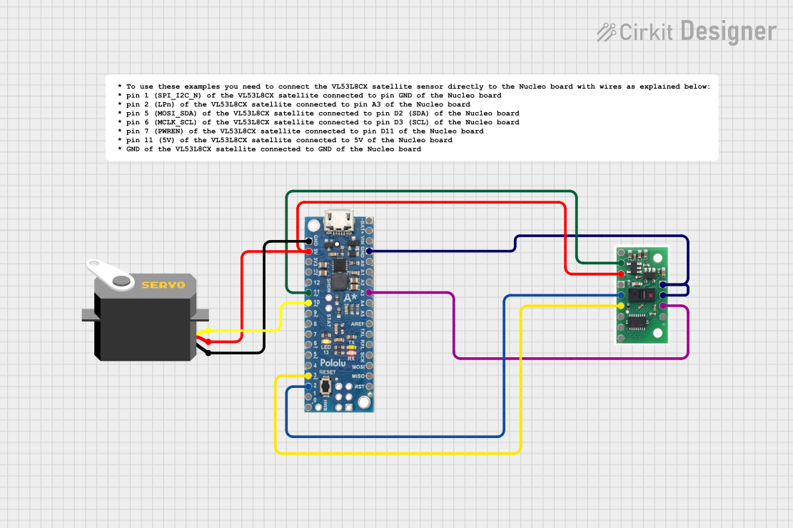
A-Star 32U4 Mini Controlled Servo with VL53L8CX Time-of-Flight Distance Sensing
Image of Servo con distance sensor: A project utilizing VL53L0X Flight Time Sensor in a practical application
This circuit features an A-Star 32U4 Mini microcontroller connected to a VL53L8CX Time-of-Flight distance sensor and a servo motor. The microcontroller powers both the sensor and the servo, and it is configured to communicate with the sensor via I2C (using pins 2 and 3 for SDA and SCL, respectively) and to control the servo via a PWM signal on pin 10. The purpose of the circuit is likely to measure distances and respond with movements of the servo based on the sensor readings.
Cirkit Designer LogoOpen Project in Cirkit Designer
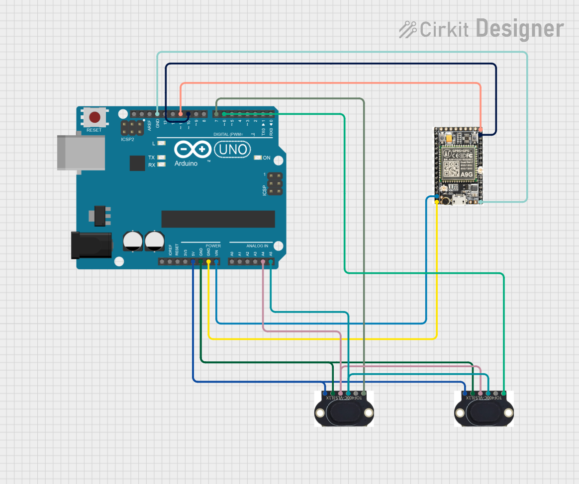
Arduino UNO with A9G GSM/GPRS and Dual VL53L1X Distance Sensors
Image of TED CIRCUIT : A project utilizing VL53L0X Flight Time Sensor in a practical application
This circuit features an Arduino UNO microcontroller interfaced with an A9G GSM/GPRS+GPS/BDS module and two VL53L1X time-of-flight distance sensors. The A9G module is connected to the Arduino via serial communication for GPS and GSM functionalities, while both VL53L1X sensors are connected through I2C with shared SDA and SCL lines and individual SHUT pins for selective sensor activation. The Arduino is programmed to control these peripherals, although the specific functionality is not detailed in the provided code.
Cirkit Designer LogoOpen Project in Cirkit Designer
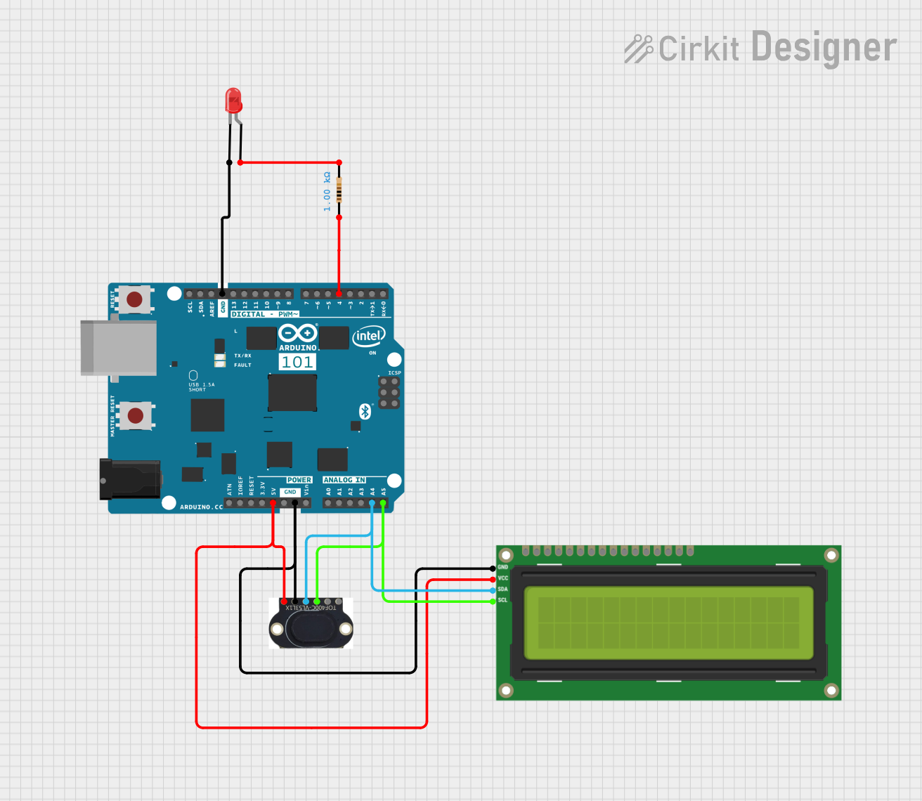
Arduino 101 Controlled Distance Measurement and Display with VL53L1X and I2C LCD
Image of TOF project: A project utilizing VL53L0X Flight Time Sensor in a practical application
This circuit features an Arduino 101 microcontroller interfaced with a VL53L1X time-of-flight distance sensor and an I2C LCD 16x2 display. The Arduino provides power to both the sensor and the display and communicates with them via the I2C bus (SDA/SCL lines). Additionally, there is a red LED with a series resistor connected to one of the Arduino's digital pins, likely for indication purposes.
Cirkit Designer LogoOpen Project in Cirkit Designer

Explore Projects Built with VL53L0X Flight Time Sensor

Use Cirkit Designer to design, explore, and prototype these projects online. Some projects support real-time simulation. Click "Open Project" to start designing instantly!
Image of Copy of test 2 (7): A project utilizing VL53L0X Flight Time Sensor in a practical application
ESP8266 NodeMCU-Based Smart Eye Pressure Monitor with OLED Display and Wi-Fi Connectivity
This circuit features an ESP8266 NodeMCU microcontroller interfaced with a VL53L0X time-of-flight distance sensor, a 0.96" OLED display, a piezo sensor, and a photodiode for light detection. The ESP8266 collects data from the sensors, displays readings on the OLED, and hosts a web server to present the information. It is likely designed for distance measurement, light intensity detection, and pressure sensing, with the capability to monitor and display these parameters in real-time over WiFi.
Cirkit Designer LogoOpen Project in Cirkit Designer
Image of Servo con distance sensor: A project utilizing VL53L0X Flight Time Sensor in a practical application
A-Star 32U4 Mini Controlled Servo with VL53L8CX Time-of-Flight Distance Sensing
This circuit features an A-Star 32U4 Mini microcontroller connected to a VL53L8CX Time-of-Flight distance sensor and a servo motor. The microcontroller powers both the sensor and the servo, and it is configured to communicate with the sensor via I2C (using pins 2 and 3 for SDA and SCL, respectively) and to control the servo via a PWM signal on pin 10. The purpose of the circuit is likely to measure distances and respond with movements of the servo based on the sensor readings.
Cirkit Designer LogoOpen Project in Cirkit Designer
Image of TED CIRCUIT : A project utilizing VL53L0X Flight Time Sensor in a practical application
Arduino UNO with A9G GSM/GPRS and Dual VL53L1X Distance Sensors
This circuit features an Arduino UNO microcontroller interfaced with an A9G GSM/GPRS+GPS/BDS module and two VL53L1X time-of-flight distance sensors. The A9G module is connected to the Arduino via serial communication for GPS and GSM functionalities, while both VL53L1X sensors are connected through I2C with shared SDA and SCL lines and individual SHUT pins for selective sensor activation. The Arduino is programmed to control these peripherals, although the specific functionality is not detailed in the provided code.
Cirkit Designer LogoOpen Project in Cirkit Designer
Image of TOF project: A project utilizing VL53L0X Flight Time Sensor in a practical application
Arduino 101 Controlled Distance Measurement and Display with VL53L1X and I2C LCD
This circuit features an Arduino 101 microcontroller interfaced with a VL53L1X time-of-flight distance sensor and an I2C LCD 16x2 display. The Arduino provides power to both the sensor and the display and communicates with them via the I2C bus (SDA/SCL lines). Additionally, there is a red LED with a series resistor connected to one of the Arduino's digital pins, likely for indication purposes.
Cirkit Designer LogoOpen Project in Cirkit Designer

Common Applications:

  • Obstacle detection in robotics and drones
  • Gesture recognition systems
  • Proximity sensing in consumer electronics
  • Distance measurement in industrial automation

Technical Specifications

Below are the key technical details of the VL53L0X sensor:

Parameter Value
Operating Voltage 2.6V to 3.5V
Communication Interface I2C (up to 400 kHz)
Measurement Range 30mm to 2000mm (2 meters)
Accuracy ±3% (typical)
Field of View (FoV) 25°
Operating Temperature -20°C to +70°C
Power Consumption 20mW (typical during operation)
Dimensions 4.4mm x 2.4mm x 1.0mm

Pin Configuration and Descriptions

The VL53L0X sensor typically comes in a breakout board format. Below is the pinout for the breakout board:

Pin Name Description
VIN Power supply input (2.6V to 5V)
GND Ground
SDA I2C data line
SCL I2C clock line
XSHUT Shutdown pin (active low, optional)
GPIO1 Interrupt output (optional, configurable)

Usage Instructions

Connecting the VL53L0X to an Arduino UNO

To use the VL53L0X with an Arduino UNO, follow these steps:

  1. Connect the VIN pin of the VL53L0X to the 5V pin on the Arduino.
  2. Connect the GND pin of the VL53L0X to the GND pin on the Arduino.
  3. Connect the SDA pin of the VL53L0X to the A4 pin on the Arduino (I2C data line).
  4. Connect the SCL pin of the VL53L0X to the A5 pin on the Arduino (I2C clock line).
  5. Optionally, connect the XSHUT pin to a digital pin on the Arduino for enabling/disabling the sensor.

Sample Arduino Code

Below is an example Arduino sketch to read distance measurements from the VL53L0X sensor using the Adafruit VL53L0X library:

#include <Wire.h>
#include <Adafruit_VL53L0X.h>

// Create an instance of the VL53L0X sensor
Adafruit_VL53L0X lox = Adafruit_VL53L0X();

void setup() {
  Serial.begin(9600); // Initialize serial communication
  while (!Serial) {
    delay(10); // Wait for the serial monitor to open
  }

  Serial.println("VL53L0X Test");

  // Initialize the sensor
  if (!lox.begin()) {
    Serial.println("Failed to initialize VL53L0X sensor!");
    while (1); // Halt execution if initialization fails
  }
}

void loop() {
  VL53L0X_RangingMeasurementData_t measure;

  // Perform a distance measurement
  lox.rangingTest(&measure, false);

  // Check if the measurement is valid
  if (measure.RangeStatus != 4) { // 4 means "out of range"
    Serial.print("Distance (mm): ");
    Serial.println(measure.RangeMilliMeter);
  } else {
    Serial.println("Out of range");
  }

  delay(100); // Wait 100ms before the next measurement
}

Important Considerations:

  • Ensure pull-up resistors (typically 4.7kΩ) are connected to the SDA and SCL lines if not already present on the breakout board.
  • Avoid exposing the sensor to direct sunlight or reflective surfaces, as this may affect accuracy.
  • Use the XSHUT pin to reset the sensor if multiple VL53L0X sensors are used on the same I2C bus.

Troubleshooting and FAQs

Common Issues and Solutions

  1. Sensor not detected on the I2C bus:

    • Ensure the wiring is correct and the connections are secure.
    • Verify that the I2C address of the sensor matches the one used in the code (default is 0x29).
    • Check if pull-up resistors are present on the SDA and SCL lines.
  2. Incorrect or fluctuating distance readings:

    • Ensure the sensor is not pointed at highly reflective or transparent surfaces.
    • Avoid using the sensor in environments with excessive ambient light.
    • Verify that the sensor is mounted securely and not vibrating.
  3. "Out of range" error:

    • Ensure the object being measured is within the sensor's range (30mm to 2000mm).
    • Check for obstructions in the sensor's field of view.

FAQs

Q: Can I use multiple VL53L0X sensors on the same I2C bus?
A: Yes, but you must change the I2C address of each sensor using the XSHUT pin to avoid address conflicts.

Q: What is the maximum distance the VL53L0X can measure?
A: The sensor can measure distances up to 2 meters (2000mm) under optimal conditions.

Q: Does the VL53L0X require calibration?
A: The sensor is factory-calibrated, but additional calibration may be needed for specific applications or environments.

Q: Can the VL53L0X detect transparent objects?
A: No, the sensor may struggle to detect transparent or highly reflective objects accurately.