
Cirkit Designer
Your all-in-one circuit design IDE
Home /
Component Documentation
How to Use Planetary gearbox motor: Examples, Pinouts, and Specs
 Design with Planetary gearbox motor in Cirkit Designer
Introduction
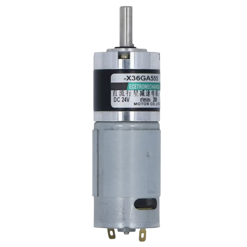
- A planetary gearbox motor is a type of motor integrated with a planetary gear system, which consists of a central sun gear, planet gears, and an outer ring gear. This design provides high torque output, compact size, and efficient power transmission.
- Common applications include robotics, industrial automation, electric vehicles, medical devices, and precision machinery where high torque and compact design are essential.
Explore Projects Built with Planetary gearbox motor
Arduino Mega 2560 Controlled Motor System with LCD Display and Keypad Interface
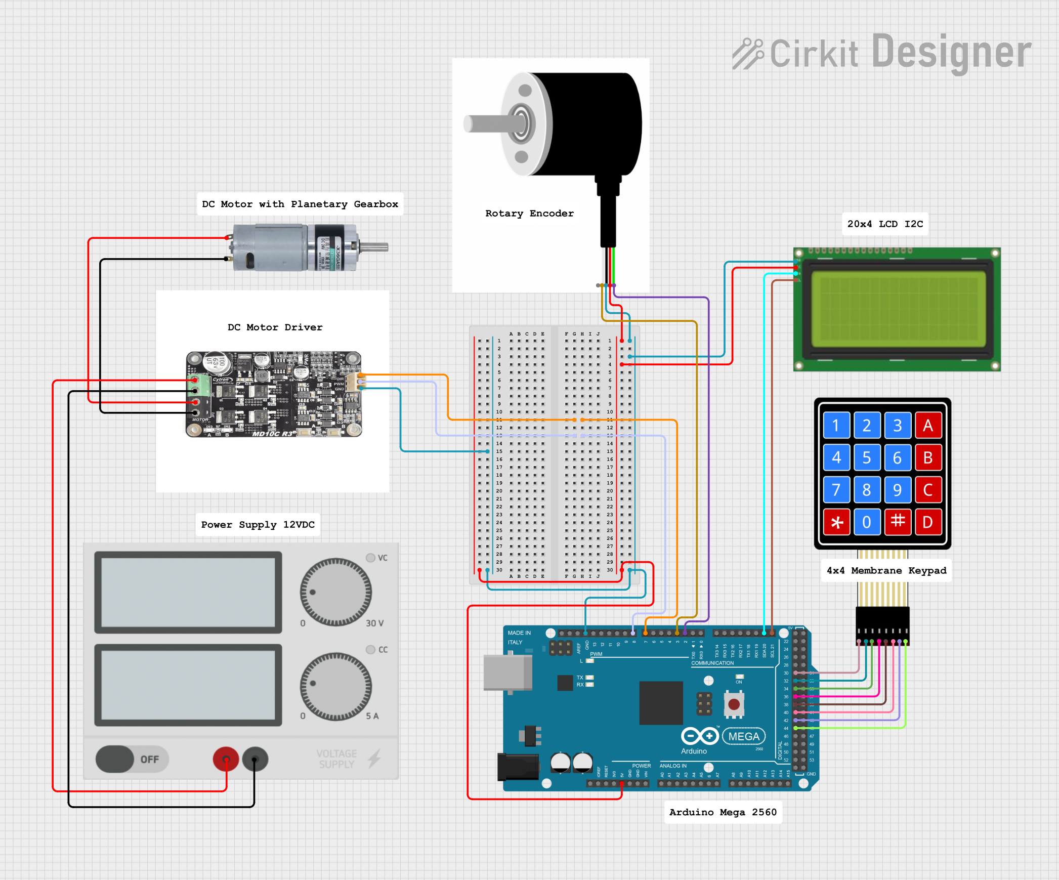
This circuit is a motor control system using an Arduino Mega 2560, which interfaces with a motor driver to control an MRB Planetary gearbox motor. It includes a rotary encoder for feedback, an LCD display for user interface, and a 4x4 membrane keypad for input, all powered by a central power supply.
Open Project in Cirkit DesignerArduino UNO Controlled Bluetooth Robotic Vehicle with L298N Motor Driver

This circuit features an Arduino UNO microcontroller interfaced with an L298N DC motor driver to control multiple MRB Planetary gearbox motors. The HC-05 Bluetooth Module is connected to the Arduino for wireless communication, allowing remote control of the motors. A 12V battery powers the system, with a buck converter stepping down the voltage to supply the Arduino and the Bluetooth module.
Open Project in Cirkit DesignerDual Motor Control System with DPDT Switches and Planetary Gearbox Motors
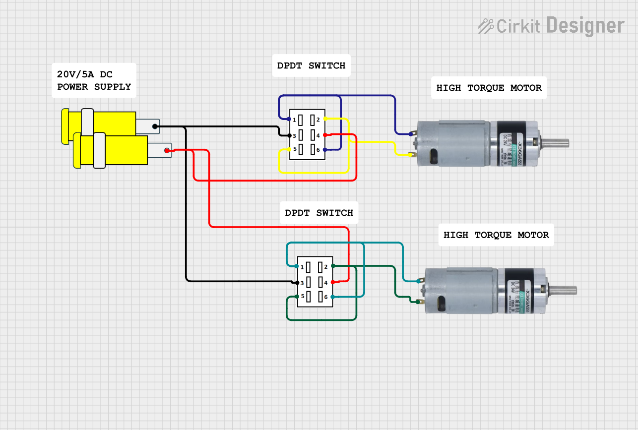
This circuit features two DPDT switches that control the direction of two MRB Planetary gearbox motors. The switches are connected to a connector, allowing for external control inputs to change the motor directions.
Open Project in Cirkit DesignerESP32-Controlled Robotics Interface with AC Synchronous Motor and L298N H-Bridge
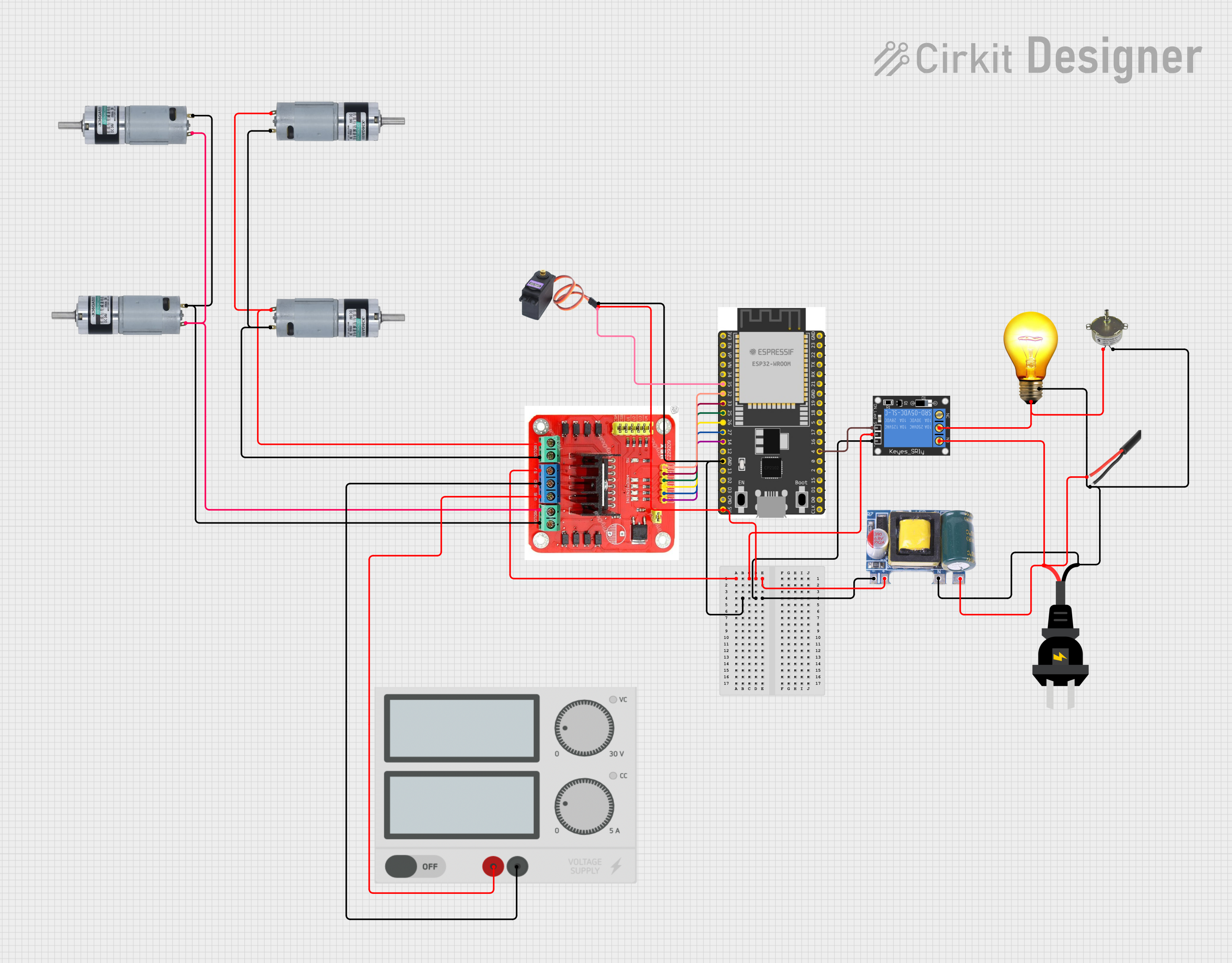
This circuit controls a set of MRB Planetary gearbox motors and an AC synchronous motor using an ESP32 microcontroller. The ESP32 interfaces with an L298N Dual H Bridge for motor control and a 1-Channel Relay to switch an AC bulb and the AC synchronous motor. A Mini AC-DC module provides 5V power to the ESP32, the relay, and the servo motor (MG996R), while the main power supply drives the L298N and the gearbox motors.
Open Project in Cirkit DesignerExplore Projects Built with Planetary gearbox motor
Arduino Mega 2560 Controlled Motor System with LCD Display and Keypad Interface
This circuit is a motor control system using an Arduino Mega 2560, which interfaces with a motor driver to control an MRB Planetary gearbox motor. It includes a rotary encoder for feedback, an LCD display for user interface, and a 4x4 membrane keypad for input, all powered by a central power supply.
Open Project in Cirkit DesignerArduino UNO Controlled Bluetooth Robotic Vehicle with L298N Motor Driver
This circuit features an Arduino UNO microcontroller interfaced with an L298N DC motor driver to control multiple MRB Planetary gearbox motors. The HC-05 Bluetooth Module is connected to the Arduino for wireless communication, allowing remote control of the motors. A 12V battery powers the system, with a buck converter stepping down the voltage to supply the Arduino and the Bluetooth module.
Open Project in Cirkit DesignerDual Motor Control System with DPDT Switches and Planetary Gearbox Motors
This circuit features two DPDT switches that control the direction of two MRB Planetary gearbox motors. The switches are connected to a connector, allowing for external control inputs to change the motor directions.
Open Project in Cirkit DesignerESP32-Controlled Robotics Interface with AC Synchronous Motor and L298N H-Bridge
This circuit controls a set of MRB Planetary gearbox motors and an AC synchronous motor using an ESP32 microcontroller. The ESP32 interfaces with an L298N Dual H Bridge for motor control and a 1-Channel Relay to switch an AC bulb and the AC synchronous motor. A Mini AC-DC module provides 5V power to the ESP32, the relay, and the servo motor (MG996R), while the main power supply drives the L298N and the gearbox motors.
Open Project in Cirkit DesignerTechnical Specifications
- Motor Type: DC motor with planetary gearbox
- Voltage Range: 6V to 24V (varies by model)
- Torque Output: Up to 50 Nm (depending on gear ratio and motor size)
- Gear Ratios: Typically available from 4:1 to 100:1
- No-Load Speed: 10 RPM to 500 RPM (varies by gear ratio)
- Efficiency: Up to 90% (depending on load and operating conditions)
- Shaft Diameter: 6mm to 12mm (varies by model)
- Operating Temperature: -20°C to 60°C
Pin Configuration and Descriptions
| Pin/Connection | Description |
|---|---|
| Motor Terminal + | Positive terminal for motor power supply |
| Motor Terminal - | Negative terminal for motor power supply |
| Encoder A (optional) | Encoder signal A for speed/direction feedback |
| Encoder B (optional) | Encoder signal B for speed/direction feedback |
| Ground (optional) | Common ground for encoder signals |
Usage Instructions
Wiring the Motor:
- Connect the motor terminals to a DC power supply or motor driver. Ensure the voltage matches the motor's rated voltage.
- If the motor includes an encoder, connect the encoder pins (A, B, and Ground) to a microcontroller or motor controller for feedback.
Using with an Arduino UNO:
- To control the motor, use a motor driver (e.g., L298N or L293D) to handle the current requirements.
- Below is an example Arduino code to control the motor's speed and direction using PWM:
// Define motor driver pins
const int motorPin1 = 9;  // Motor terminal 1 (connected to motor driver)
const int motorPin2 = 10; // Motor terminal 2 (connected to motor driver)
const int pwmPin = 11;    // PWM pin for speed control

void setup() {
  // Set motor pins as outputs
  pinMode(motorPin1, OUTPUT);
  pinMode(motorPin2, OUTPUT);
  pinMode(pwmPin, OUTPUT);
}

void loop() {
  // Rotate motor forward
  digitalWrite(motorPin1, HIGH); // Set motorPin1 HIGH
  digitalWrite(motorPin2, LOW);  // Set motorPin2 LOW
  analogWrite(pwmPin, 128);      // Set speed (0-255, 128 = 50% duty cycle)
  delay(2000);                   // Run for 2 seconds

  // Rotate motor backward
  digitalWrite(motorPin1, LOW);  // Set motorPin1 LOW
  digitalWrite(motorPin2, HIGH); // Set motorPin2 HIGH
  analogWrite(pwmPin, 128);      // Set speed (0-255, 128 = 50% duty cycle)
  delay(2000);                   // Run for 2 seconds

  // Stop motor
  digitalWrite(motorPin1, LOW);  // Set motorPin1 LOW
  digitalWrite(motorPin2, LOW);  // Set motorPin2 LOW
  delay(2000);                   // Stop for 2 seconds
}
- Important Considerations:
- Always check the motor's voltage and current ratings before connecting to a power source.
- Use a motor driver or controller to prevent damage to the motor or microcontroller.
- If using an encoder, ensure proper pull-up resistors are used for reliable signal reading.
Troubleshooting and FAQs
Common Issues
Motor does not rotate:
- Check the power supply voltage and ensure it matches the motor's rated voltage.
- Verify the motor driver connections and ensure the control signals are correct.
- Inspect for loose or damaged wires.
Motor rotates in the wrong direction:
- Swap the connections of the motor terminals or adjust the control signals in the code.
Motor overheats:
- Ensure the motor is not overloaded beyond its torque rating.
- Check for proper ventilation and avoid prolonged operation at maximum load.
Encoder signals are inconsistent:
- Verify the encoder wiring and ensure proper pull-up resistors are used.
- Check for electrical noise and use shielded cables if necessary.
FAQs
Can I use a planetary gearbox motor with an AC power supply?
- No, planetary gearbox motors are typically DC motors. Use a DC power supply or a rectifier to convert AC to DC.
What gear ratio should I choose?
- Select a gear ratio based on the required torque and speed for your application. Higher gear ratios provide more torque but reduce speed.
Can I run the motor without a motor driver?
- It is not recommended, as the motor driver protects the motor and microcontroller from high currents and provides better control.
How do I calculate the output speed of the motor?
- Output speed = Motor speed ÷ Gear ratio. For example, if the motor speed is 3000 RPM and the gear ratio is 10:1, the output speed is 300 RPM.