How to Use UFM-02 translation board: Examples, Pinouts, and Specs
Introduction
The UFM-02 Translation Board by ScioSense (Part ID: UFM02_Translation_Board) is a versatile circuit board designed to translate signals between different formats or protocols. It is commonly used in communication systems to interface between devices that operate on incompatible signal standards. This board simplifies the integration of various components in a system, ensuring seamless communication and data transfer.
Explore Projects Built with UFM-02 translation board


Explore Projects Built with UFM-02 translation board
Common Applications and Use Cases
- Protocol Conversion: Translating between UART, I2C, SPI, or other communication protocols.
- Signal Level Shifting: Converting voltage levels (e.g., 3.3V to 5V or vice versa).
- Device Interfacing: Connecting microcontrollers, sensors, and other peripherals with differing communication standards.
- Embedded Systems: Used in IoT devices, industrial automation, and consumer electronics.
Technical Specifications
Key Technical Details
- Input Voltage Range: 3.0V to 5.5V
- Output Voltage Range: 3.0V to 5.5V (configurable)
- Supported Protocols: UART, I2C, SPI
- Maximum Data Rate: 1 Mbps (depending on protocol and configuration)
- Operating Temperature: -40°C to +85°C
- Dimensions: 25mm x 20mm x 5mm
- Power Consumption: < 50mW (typical)
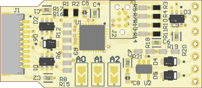
Pin Configuration and Descriptions
The UFM-02 Translation Board features a standard pinout for easy integration. Below is the pin configuration:
| Pin | Name | Description |
|---|---|---|
| 1 | VCC | Power supply input (3.0V to 5.5V). Connect to the power source. |
| 2 | GND | Ground connection. |
| 3 | IN1 | Input signal for Channel 1. |
| 4 | OUT1 | Output signal for Channel 1. |
| 5 | IN2 | Input signal for Channel 2. |
| 6 | OUT2 | Output signal for Channel 2. |
| 7 | SDA_IN | I2C data input (used in I2C mode). |
| 8 | SDA_OUT | I2C data output (used in I2C mode). |
| 9 | SCL_IN | I2C clock input (used in I2C mode). |
| 10 | SCL_OUT | I2C clock output (used in I2C mode). |
| 11 | CS | Chip select (used in SPI mode). |
| 12 | MOSI | Master Out Slave In (used in SPI mode). |
| 13 | MISO | Master In Slave Out (used in SPI mode). |
| 14 | SCK | Serial clock (used in SPI mode). |
Usage Instructions
How to Use the Component in a Circuit
- Power the Board: Connect the VCC pin to a power source (3.0V to 5.5V) and the GND pin to ground.
- Select the Protocol: Determine the communication protocol (UART, I2C, or SPI) required for your application.
- For UART, use the IN1 and OUT1 pins for data transmission.
- For I2C, connect SDA_IN, SDA_OUT, SCL_IN, and SCL_OUT to the respective I2C lines.
- For SPI, connect CS, MOSI, MISO, and SCK to the SPI bus.
- Connect the Devices: Attach the devices to the appropriate input and output pins based on the selected protocol.
- Configure Voltage Levels: Ensure the input and output voltage levels are compatible with the connected devices. Use external pull-up resistors if required for I2C communication.
- Test the Setup: Verify the signal translation using an oscilloscope or logic analyzer.
Important Considerations and Best Practices
- Voltage Compatibility: Ensure the input and output voltage levels match the requirements of the connected devices.
- Pull-Up Resistors: For I2C communication, use pull-up resistors on the SDA and SCL lines if they are not already present in the circuit.
- Signal Integrity: Keep the wiring between the UFM-02 Translation Board and other devices as short as possible to minimize noise and signal degradation.
- Protocol Selection: Only use one protocol (UART, I2C, or SPI) at a time to avoid conflicts.
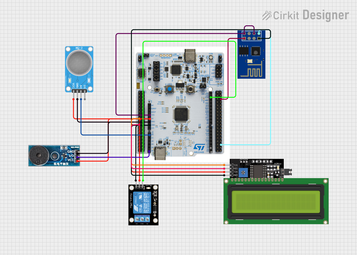
Example: Using the UFM-02 with an Arduino UNO
Below is an example of using the UFM-02 Translation Board to interface an Arduino UNO with an I2C sensor operating at 3.3V:
Circuit Connections
- Connect the Arduino's 5V pin to the UFM-02's VCC pin.
- Connect the Arduino's GND pin to the UFM-02's GND pin.
- Connect the Arduino's SDA (A4) and SCL (A5) pins to the UFM-02's SDA_IN and SCL_IN pins, respectively.
- Connect the sensor's SDA and SCL pins to the UFM-02's SDA_OUT and SCL_OUT pins.
Arduino Code
#include <Wire.h> // Include the Wire library for I2C communication

void setup() {
  Wire.begin(); // Initialize I2C communication
  Serial.begin(9600); // Start serial communication for debugging

  // Send a test message to the I2C device
  Wire.beginTransmission(0x40); // Replace 0x40 with the I2C address of your device
  Wire.write(0x00); // Example: Write a command or register address
  Wire.endTransmission();

  Serial.println("I2C communication initialized.");
}

void loop() {
  // Example: Read data from the I2C device
  Wire.requestFrom(0x40, 2); // Request 2 bytes from the device at address 0x40
  if (Wire.available()) {
    int data = Wire.read(); // Read the first byte
    Serial.print("Data received: ");
    Serial.println(data);
  }
  delay(1000); // Wait 1 second before the next read
}
Troubleshooting and FAQs
Common Issues and Solutions
No Signal Translation
- Cause: Incorrect power supply or loose connections.
- Solution: Verify the VCC and GND connections and ensure the power supply is within the specified range.
Data Corruption
- Cause: Signal noise or mismatched voltage levels.
- Solution: Use shorter wires, add decoupling capacitors, and ensure voltage levels are compatible.
I2C Communication Fails
- Cause: Missing pull-up resistors on SDA and SCL lines.
- Solution: Add 4.7kΩ pull-up resistors to the SDA and SCL lines.
SPI Communication Issues
- Cause: Incorrect clock polarity or phase settings.
- Solution: Check the SPI settings (CPOL and CPHA) in your microcontroller's configuration.
FAQs
Q: Can the UFM-02 handle bidirectional communication?
A: Yes, the UFM-02 supports bidirectional communication for protocols like I2C.Q: What is the maximum data rate supported?
A: The UFM-02 supports data rates up to 1 Mbps, depending on the protocol and configuration.Q: Is the UFM-02 compatible with 1.8V devices?
A: No, the UFM-02 is designed for 3.0V to 5.5V operation. Use a level shifter for 1.8V devices.Q: Can I use multiple protocols simultaneously?
A: No, only one protocol (UART, I2C, or SPI) should be used at a time to avoid conflicts.