
How to Use MAX7456: Examples, Pinouts, and Specs
 Design with MAX7456 in Cirkit Designer
Introduction
The MAX7456 is a monochrome on-screen display (OSD) generator designed to overlay text and graphics onto video signals. It simplifies the process of adding custom information, such as telemetry data, to video feeds. The device is widely used in applications like video cameras, drones, security systems, and other video-based systems requiring real-time data display.
The MAX7456 supports NTSC and PAL video standards, making it versatile for global applications. It features an internal character memory and supports user-defined character sets, allowing for highly customizable displays.
Explore Projects Built with MAX7456
 Open Project in Cirkit Designer
 Open Project in Cirkit Designer
 Open Project in Cirkit Designer
 Open Project in Cirkit Designer
Explore Projects Built with MAX7456
Open Project in Cirkit DesignerOpen Project in Cirkit DesignerOpen Project in Cirkit DesignerOpen Project in Cirkit DesignerTechnical Specifications
- Video Standards Supported: NTSC and PAL
- Operating Voltage: 4.75V to 5.25V
- Power Consumption: 100mW (typical)
- Character Memory: Internal 256-character memory (programmable)
- Input/Output Video Impedance: 75Ω
- Operating Temperature Range: -40°C to +85°C
- Communication Interface: SPI (Serial Peripheral Interface)
Pin Configuration and Descriptions
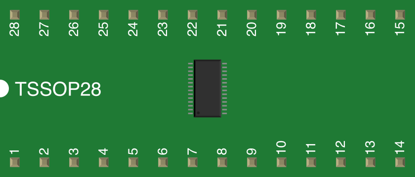
The MAX7456 is available in a 28-pin package. Below is the pin configuration and description:
| Pin Number | Pin Name | Description |
|---|---|---|
| 1 | GND | Ground connection. |
| 2 | VDD | Power supply input (4.75V to 5.25V). |
| 3 | CS | Chip Select for SPI communication. Active low. |
| 4 | SCLK | SPI clock input. |
| 5 | MOSI | SPI Master Out Slave In (data input). |
| 6 | MISO | SPI Master In Slave Out (data output). |
| 7 | RESET | Active-low reset input. |
| 8 | VIDEO_IN | Composite video input. |
| 9 | VIDEO_OUT | Composite video output with OSD overlay. |
| 10 | GND | Ground connection. |
| 11-28 | NC | No connection (reserved for future use). |
Usage Instructions
How to Use the MAX7456 in a Circuit
- Power Supply: Connect the VDD pin to a regulated 5V power supply and GND to ground.
- Video Signal: Feed the composite video signal into the VIDEO_IN pin. The processed video with OSD overlay will be available at the VIDEO_OUT pin.
- SPI Communication: Use the SPI interface (CS, SCLK, MOSI, MISO) to configure the MAX7456 and send character data. Ensure the SPI clock speed does not exceed 8MHz.
- Character Memory: Program the internal character memory with custom fonts or graphics if needed. This is done via SPI commands.
- Reset: Use the RESET pin to initialize the device during power-up or after a fault condition.
Important Considerations and Best Practices
- Video Signal Impedance: Ensure proper termination of the video signal with a 75Ω resistor to maintain signal integrity.
- Decoupling Capacitors: Place decoupling capacitors (e.g., 0.1µF) close to the VDD pin to reduce noise.
- SPI Configuration: Configure the SPI interface in Mode 0 (CPOL = 0, CPHA = 0) for proper communication.
- Character Memory Programming: Use the provided datasheet instructions to program custom characters. This process is non-volatile, meaning the data will persist after power cycling.
Example Code for Arduino UNO
Below is an example of how to interface the MAX7456 with an Arduino UNO to display text on a video signal:
#include <SPI.h>

// Define MAX7456 SPI pins
#define MAX7456_CS 10  // Chip Select pin connected to Arduino pin 10

void setup() {
  // Initialize SPI communication
  SPI.begin();
  SPI.setClockDivider(SPI_CLOCK_DIV16); // Set SPI clock speed
  SPI.setDataMode(SPI_MODE0);          // Set SPI mode (CPOL = 0, CPHA = 0)
  pinMode(MAX7456_CS, OUTPUT);
  digitalWrite(MAX7456_CS, HIGH);      // Set CS pin high (inactive)

  // Initialize MAX7456
  initializeMAX7456();
}

void loop() {
  // Example: Display "HELLO" on the screen
  displayText("HELLO");
}

void initializeMAX7456() {
  digitalWrite(MAX7456_CS, LOW);       // Select MAX7456
  SPI.transfer(0x00);                  // Example: Write to a control register
  SPI.transfer(0x48);                  // Example value to enable OSD
  digitalWrite(MAX7456_CS, HIGH);      // Deselect MAX7456
}

void displayText(const char* text) {
  digitalWrite(MAX7456_CS, LOW);       // Select MAX7456
  for (int i = 0; text[i] != '\0'; i++) {
    SPI.transfer(0x01);                // Example: Write to character memory
    SPI.transfer(text[i]);             // Send character data
  }
  digitalWrite(MAX7456_CS, HIGH);      // Deselect MAX7456
}
Troubleshooting and FAQs
Common Issues
No OSD Output on Video Signal:
- Ensure the video signal is properly connected to the VIDEO_IN pin.
- Verify that the SPI communication is correctly configured and operational.
- Check the power supply voltage and ensure it is within the specified range (4.75V to 5.25V).
Corrupted or Missing Characters:
- Verify that the character memory is programmed correctly.
- Ensure the SPI clock speed does not exceed 8MHz.
Device Not Responding to SPI Commands:
- Check the connections for the CS, SCLK, MOSI, and MISO pins.
- Ensure the SPI mode is set to Mode 0 (CPOL = 0, CPHA = 0).
Tips for Troubleshooting
- Use an oscilloscope to verify the integrity of the video signal at the VIDEO_IN and VIDEO_OUT pins.
- Monitor the SPI signals (SCLK, MOSI, MISO) to ensure proper communication.
- If the device is unresponsive, try resetting it using the RESET pin.
By following this documentation, users can effectively integrate the MAX7456 into their projects and troubleshoot common issues.