How to Use MAX3485EPA+-ND IC TRANSCEIVER HALF 1/1 8PDIP: Examples, Pinouts, and Specs
Introduction
The MAX3485EPA+-ND is a half-duplex RS-485/RS-422 transceiver manufactured by Analog Devices Inc./Maxim Integrated. It is designed for robust and reliable data communication over long distances, supporting differential signaling to minimize noise and signal degradation. This transceiver operates with low power consumption and is optimized for industrial environments, offering a wide voltage range and high-speed data transmission.
Explore Projects Built with MAX3485EPA+-ND IC TRANSCEIVER HALF 1/1 8PDIP


Explore Projects Built with MAX3485EPA+-ND IC TRANSCEIVER HALF 1/1 8PDIP
Common Applications and Use Cases
- Industrial automation and control systems
- Building automation (e.g., HVAC systems)
- Data acquisition systems
- Long-distance communication networks
- RS-485/RS-422-based serial communication interfaces
Technical Specifications
Key Technical Details
| Parameter | Value |
|---|---|
| Supply Voltage (Vcc) | 3.3V to 5.5V |
| Data Rate | Up to 10 Mbps |
| Operating Temperature | -40°C to +85°C |
| Driver Output Voltage | -7V to +12V |
| Receiver Input Resistance | ≥ 96 kΩ |
| Low Power Shutdown Mode | 1 µA (typical) |
| Package Type | 8-pin DIP |
| Communication Mode | Half-duplex |
Pin Configuration and Descriptions
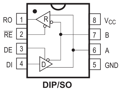
The MAX3485EPA+-ND is housed in an 8-pin DIP package. The pinout and descriptions are as follows:
| Pin Number | Pin Name | Description |
|---|---|---|
| 1 | RO | Receiver Output: Outputs the received data. |
| 2 | RE̅ | Receiver Enable: Active-low input to enable the receiver. |
| 3 | DE | Driver Enable: Enables the driver when high. |
| 4 | DI | Driver Input: Accepts the data to be transmitted. |
| 5 | GND | Ground: Connect to system ground. |
| 6 | A | Non-inverting Driver Output / Receiver Input. |
| 7 | B | Inverting Driver Output / Receiver Input. |
| 8 | Vcc | Power Supply: Connect to 3.3V or 5V supply. |
Usage Instructions
How to Use the Component in a Circuit
- Power Supply: Connect the Vcc pin to a 3.3V or 5V power supply and the GND pin to the system ground.
- Data Transmission:
- Connect the DI pin to the microcontroller or data source for transmitting data.
- Use the DE pin to enable the driver. Set DE high to enable transmission.
- Data Reception:
- Connect the RO pin to the microcontroller or data sink for receiving data.
- Use the RE̅ pin to enable the receiver. Set RE̅ low to enable reception.
- Differential Signal Lines:
- Connect the A and B pins to the RS-485/RS-422 bus. Ensure proper termination resistors are used at both ends of the bus to prevent signal reflections.
- Termination Resistors: Use a 120Ω resistor between A and B at each end of the bus for proper impedance matching.
Important Considerations and Best Practices
- Bus Length: Ensure the total bus length does not exceed the RS-485 standard limit (typically 1200 meters).
- Termination: Always use termination resistors to maintain signal integrity.
- Biasing Resistors: Add pull-up and pull-down resistors on the A and B lines to ensure a known idle state when no driver is active.
- Electrostatic Discharge (ESD) Protection: Use external TVS diodes or other ESD protection devices for robust operation in noisy environments.
- Low Power Mode: To save power, disable both the driver and receiver by setting DE low and RE̅ high.
Example Arduino UNO Code
Below is an example of how to use the MAX3485EPA+-ND with an Arduino UNO for basic RS-485 communication:
// Example: RS-485 Communication using MAX3485EPA+-ND with Arduino UNO

#define DE_PIN 2  // Driver Enable pin connected to Arduino pin 2
#define RE_PIN 3  // Receiver Enable pin connected to Arduino pin 3
#define DI_PIN 4  // Driver Input pin connected to Arduino pin 4
#define RO_PIN 5  // Receiver Output pin connected to Arduino pin 5

void setup() {
  pinMode(DE_PIN, OUTPUT);  // Set DE pin as output
  pinMode(RE_PIN, OUTPUT);  // Set RE pin as output
  pinMode(DI_PIN, OUTPUT);  // Set DI pin as output
  pinMode(RO_PIN, INPUT);   // Set RO pin as input

  // Initialize communication
  Serial.begin(9600);  // Set baud rate for serial communication
}

void loop() {
  // Transmit data
  digitalWrite(DE_PIN, HIGH);  // Enable driver
  digitalWrite(RE_PIN, HIGH);  // Disable receiver
  digitalWrite(DI_PIN, HIGH);  // Send a HIGH signal (logic 1)
  delay(1000);                 // Wait for 1 second
  digitalWrite(DI_PIN, LOW);   // Send a LOW signal (logic 0)
  delay(1000);                 // Wait for 1 second

  // Receive data
  digitalWrite(DE_PIN, LOW);   // Disable driver
  digitalWrite(RE_PIN, LOW);   // Enable receiver
  int receivedData = digitalRead(RO_PIN);  // Read received data
  Serial.println(receivedData);  // Print received data to Serial Monitor
}
Troubleshooting and FAQs
Common Issues and Solutions
No Communication on the Bus:
- Cause: Incorrect termination or missing termination resistors.
- Solution: Ensure 120Ω termination resistors are installed at both ends of the RS-485 bus.
Data Corruption:
- Cause: Noise or improper biasing of the A and B lines.
- Solution: Add pull-up and pull-down resistors to bias the bus and use shielded twisted-pair cables.
High Power Consumption:
- Cause: Driver and receiver are both enabled unnecessarily.
- Solution: Disable the driver and receiver when not in use to save power.
Device Overheating:
- Cause: Exceeding voltage or current ratings.
- Solution: Verify that the supply voltage is within the specified range (3.3V to 5.5V) and that the bus is not overloaded.
FAQs
Q1: Can the MAX3485EPA+-ND be used for full-duplex communication?
A1: No, the MAX3485EPA+-ND is designed for half-duplex communication only. For full-duplex communication, consider using a full-duplex RS-485 transceiver.
Q2: What is the maximum number of devices that can be connected to the RS-485 bus?
A2: The MAX3485EPA+-ND supports up to 32 devices on the RS-485 bus.
Q3: Can this transceiver operate at 3.3V?
A3: Yes, the MAX3485EPA+-ND operates with a supply voltage range of 3.3V to 5.5V.
Q4: Is the MAX3485EPA+-ND suitable for outdoor applications?
A4: While the device operates in a wide temperature range (-40°C to +85°C), additional protection (e.g., weatherproof enclosures) may be required for outdoor use.