How to Use 63a voltage protector: Examples, Pinouts, and Specs
Introduction
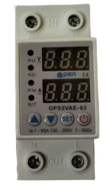
The 63A Voltage Protector is a device designed to safeguard electrical circuits from overvoltage conditions. It is rated for a maximum current of 63 amps, making it suitable for high-power applications. This component ensures the safety of connected equipment by disconnecting the circuit when voltage levels exceed a predefined threshold. It is commonly used in residential, commercial, and industrial settings to protect appliances, machinery, and other sensitive electronics from voltage surges or fluctuations.
Explore Projects Built with 63a voltage protector


Explore Projects Built with 63a voltage protector
Common Applications and Use Cases
- Protection of household appliances such as refrigerators, air conditioners, and washing machines.
- Safeguarding industrial equipment from voltage spikes.
- Ensuring stable operation of sensitive electronics in commercial environments.
- Preventing damage to electrical systems during power grid fluctuations or lightning strikes.
Technical Specifications
The following table outlines the key technical details of the 63A Voltage Protector:
| Parameter | Value |
|---|---|
| Rated Current | 63A |
| Operating Voltage Range | 220V - 240V AC |
| Overvoltage Trip Point | Typically 260V AC (adjustable) |
| Undervoltage Trip Point | Typically 180V AC (adjustable) |
| Response Time | < 1 second |
| Reset Type | Automatic or Manual (varies by model) |
| Power Consumption | < 2W |
| Operating Temperature | -10°C to 50°C |
| Dimensions | Varies by model (e.g., 90mm x 60mm x 40mm) |
| Mounting Type | DIN rail or wall-mounted |
Pin Configuration and Descriptions
The 63A Voltage Protector typically has the following terminal connections:
| Terminal | Label | Description |
|---|---|---|
| 1 | L (Line) | Connect to the live wire of the AC power supply. |
| 2 | N (Neutral) | Connect to the neutral wire of the AC power supply. |
| 3 | Load L | Connect to the live wire of the load (protected device). |
| 4 | Load N | Connect to the neutral wire of the load (protected device). |
Usage Instructions
How to Use the 63A Voltage Protector in a Circuit
- Power Off the Circuit: Ensure the power supply is turned off before installation.
- Connect the Input Terminals:
- Connect the live wire of the AC power supply to the
Lterminal. - Connect the neutral wire of the AC power supply to the
Nterminal.
- Connect the live wire of the AC power supply to the
- Connect the Output Terminals:
- Connect the live wire of the load (protected device) to the
Load Lterminal. - Connect the neutral wire of the load to the
Load Nterminal.
- Connect the live wire of the load (protected device) to the
- Secure the Connections: Tighten all terminal screws to ensure a secure connection.
- Mount the Device: Install the voltage protector on a DIN rail or wall mount as per the model's design.
- Power On the Circuit: Turn on the power supply and verify that the voltage protector is functioning correctly.
Important Considerations and Best Practices
- Voltage Settings: If the device allows adjustable overvoltage and undervoltage trip points, set them according to the requirements of your load.
- Load Capacity: Ensure the total current drawn by the connected load does not exceed 63A.
- Environment: Install the device in a dry, well-ventilated area to prevent overheating or moisture damage.
- Testing: Periodically test the voltage protector by simulating overvoltage and undervoltage conditions to ensure proper operation.
- Compatibility with Generators: If using with a generator, ensure the generator's output voltage is stable and within the operating range of the voltage protector.
Arduino Integration
While the 63A Voltage Protector is not directly programmable, it can be monitored using an Arduino UNO and a voltage sensor. Below is an example code snippet to monitor the voltage levels:
// Example code to monitor voltage levels using an Arduino UNO
// and a voltage sensor module. This can be used to verify the
// input voltage to the 63A Voltage Protector.

const int voltagePin = A0; // Analog pin connected to the voltage sensor
float voltage = 0.0;

void setup() {
  Serial.begin(9600); // Initialize serial communication
}

void loop() {
  int sensorValue = analogRead(voltagePin); // Read the sensor value
  voltage = (sensorValue * 5.0 / 1023.0) * 100;
  // Convert the analog value to voltage (assuming a 100:1 sensor ratio)

  Serial.print("Voltage: ");
  Serial.print(voltage);
  Serial.println(" V");

  delay(1000); // Wait for 1 second before the next reading
}
Note: Ensure the voltage sensor module is rated for the AC voltage range you are monitoring. Use appropriate isolation techniques when interfacing with high-voltage circuits.
Troubleshooting and FAQs
Common Issues and Solutions
| Issue | Possible Cause | Solution |
|---|---|---|
| Device does not power on | Loose or incorrect wiring | Verify all connections and tighten terminals. |
| Frequent tripping of the protector | Voltage fluctuations beyond set thresholds | Adjust the overvoltage/undervoltage settings. |
| Load not receiving power | Protector is in tripped state | Check the input voltage and reset the device. |
| Overheating of the device | Excessive load current | Ensure the load does not exceed 63A. |
FAQs
Can the trip points be adjusted?
- Yes, most models allow adjustment of overvoltage and undervoltage trip points. Refer to the specific model's manual for instructions.
What happens after a trip event?
- Depending on the model, the device may automatically reset after the voltage returns to normal, or it may require manual resetting.
Can this device protect against lightning strikes?
- While it provides some protection against voltage surges, it is recommended to use a dedicated surge protector for lightning protection.
Is it compatible with three-phase systems?
- No, this model is designed for single-phase systems. For three-phase protection, use a dedicated three-phase voltage protector.
By following this documentation, users can effectively install, use, and troubleshoot the 63A Voltage Protector to ensure the safety of their electrical systems.