How to Use Adafruit DC Boarduino: Examples, Pinouts, and Specs
Introduction
The Adafruit DC Boarduino is a versatile, breadboard-friendly development board that is compatible with the Arduino ecosystem. Designed for hobbyists, educators, and professionals, it provides a convenient platform for prototyping and creating microcontroller-based projects. The Boarduino's small form factor and compatibility with a wide range of shields make it ideal for applications where space is at a premium, such as wearable technology, compact robotics, and custom embedded systems.
Explore Projects Built with Adafruit DC Boarduino
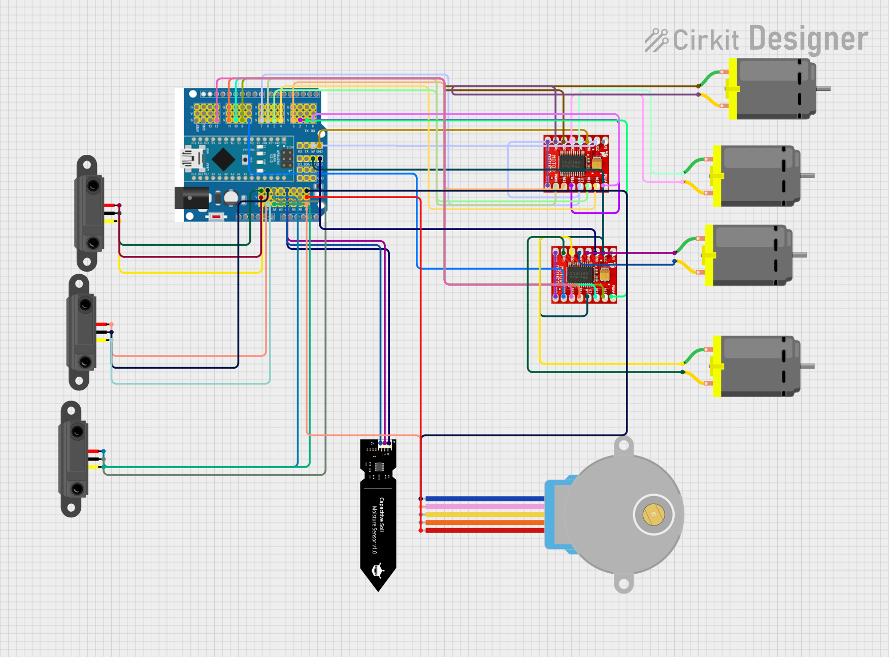
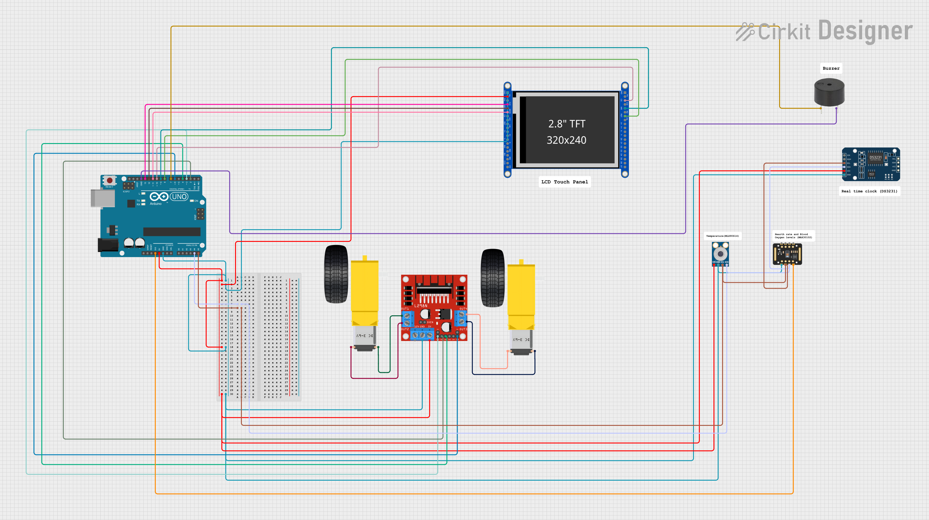
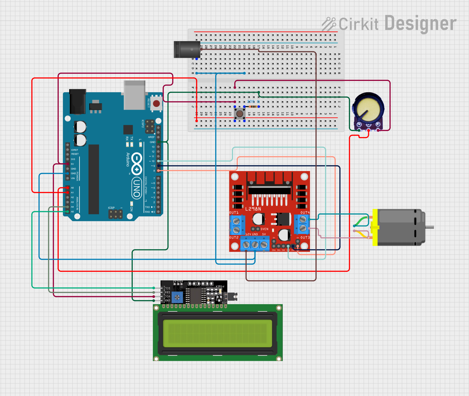
Explore Projects Built with Adafruit DC Boarduino
Technical Specifications
Key Technical Details
- Microcontroller: ATmega328P
- Operating Voltage: 5V
- Input Voltage (recommended): 7-12V
- Input Voltage (limits): 6-20V
- Digital I/O Pins: 14 (of which 6 provide PWM output)
- Analog Input Pins: 6
- DC Current per I/O Pin: 40 mA
- DC Current for 3.3V Pin: 50 mA
- Flash Memory: 32 KB (ATmega328P) of which 0.5 KB used by bootloader
- SRAM: 2 KB (ATmega328P)
- EEPROM: 1 KB (ATmega328P)
- Clock Speed: 16 MHz
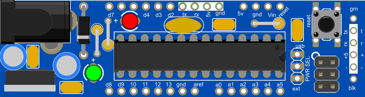
Pin Configuration and Descriptions
| Pin Number | Function | Description |
|---|---|---|
| 1 | RESET | Used to reset the microcontroller |
| 2-13 | Digital I/O | Digital input/output pins, PWM on pins 3, 5, 6, 9, 10, and 11 |
| 14-19 | Analog Input | Analog input pins (A0-A5) |
| 20 | AREF | Analog reference voltage for the ADC |
| 21 | GND | Ground |
| 22 | 3V3 | 3.3V output (from onboard regulator) |
| 23 | D13/LED | Built-in LED connected to digital pin 13 |
| 24 | 5V | Regulated 5V supply to power the microcontroller |
| 25 | GND | Ground |
| 26 | Vin | Input voltage to the onboard 5V regulator |
Usage Instructions
Integrating with a Circuit
To use the Adafruit DC Boarduino in a circuit:
- Connect the Boarduino to a breadboard.
- Supply power through the Vin pin with a DC power source between 7-12V.
- Connect the ground from the power source to one of the GND pins on the Boarduino.
- Use the digital and analog pins to interface with sensors, actuators, and other components.
Important Considerations and Best Practices
- Always ensure that the power supply voltage is within the specified limits to prevent damage.
- When connecting components, make sure the total current draw does not exceed the maximum ratings for the pins.
- Use external power when connecting high-power devices to avoid overloading the Boarduino's voltage regulator.
- Disconnect the power source when making changes to the circuit to prevent accidental shorts or component damage.
Troubleshooting and FAQs
Common Issues
- Boarduino not powering up: Check the power connections and ensure the supply voltage is within the recommended range.
- Inconsistent behavior or resets: Ensure that the power supply can provide sufficient current for the connected components.
- I/O pin not working: Verify that the pin is configured correctly in the code and that there is no short circuit or overload.
Solutions and Tips
- If the Boarduino is unresponsive, try pressing the reset button to reboot the microcontroller.
- Use a multimeter to check for proper voltage levels and continuity in your circuit.
- For complex issues, simplify your setup by disconnecting external components and testing them individually.
Example Code for Arduino UNO
Here is a simple example of how to blink the onboard LED using the Arduino IDE:
// Pin 13 has an LED connected on most Arduino boards.
int led = 13;

// The setup routine runs once when you press reset:
void setup() {
  // Initialize the digital pin as an output.
  pinMode(led, OUTPUT);
}

// The loop routine runs over and over again forever:
void loop() {
  digitalWrite(led, HIGH);   // Turn the LED on (HIGH is the voltage level)
  delay(1000);               // Wait for a second
  digitalWrite(led, LOW);    // Turn the LED off by making the voltage LOW
  delay(1000);               // Wait for a second
}
Remember to select the correct board from the Tools > Board menu in the Arduino IDE before uploading the code to the Boarduino.
For more advanced usage and additional examples, refer to the Arduino language reference and the wide array of community-contributed tutorials and projects available online.